| Measurement interface | Standard: RS-232C*1/422/485*2 Option: 2.5/3.3/5 V TTL*3 |
|
|---|---|---|
| Supporting protocol | Asynchronous (Async), Async PPP Data (5, 6, 7, and 8 bits) + parity (none, odd, even, mark, space, and MP*4) + stop (1, 1.5 and 2 bits)*5 |
|
| Baud rate | 50 bps to 250 kbps*6 | |
| Data code | ASCII, EBCDIC, JIS7, JIS8, Baudot, Transcode, IPARS, EBCD, EBCDIK, and HEX | |
| Bit transmission order | LSB first or MSB first | |
| Bit polarity | Normal or inverted | |
| Record storage | Capacity | Up to 1,000 files in 1 MB, 2 MB, 4 MB or 8 MB can be specified on HDD of the PC. |
| Mode | Fixed buffer mode (measurement finished with specified capacity used) or ring buffer mode (endless recording leaving the latest data of the specified capacity) selectable. | |
| Error check | Parity, framing, break, LRC, CRC-16, CRC-ITU-T, CRC-6, and CRC-12 | |
| Idle time | OFF (no recording) or recording in resolution of 100 ms, 10 ms or 1 ms. | |
| Time stamp | OFF (no recording) or selectable "Day/Hr/Min", "Hr/Min/Sec" and "Min/Sec/10 ms." | |
| Line status | Records RS, CS, ER, DR, CD and CI signal logic along with data. | |
| Trigger | Condition | Specified types of communication errors, communications data string up to 8 characters (don’t care and bit mask available), logic of interface signal line, match timer counter value, idle time more than the specified duration, external signal |
| Action | Stops measurement (offset can be set), controls timer/counter, enables and disables trigger conditions, sends the specified data string | |
| External trigger I/O terminal | External device and trigger signal I/O (Input: Trigger condition; Output: Active output when conditions satisfied)*8 | |
| Search function | Specified types of communication errors, communications data string up to 8 characters (don’t care and bit mask available), idle time more than the specified duration, time stamp at the specified time (don’t care can be specified), trigger matching data | |
| Simulation function | Possible to transmit 16 types of transmission data strings registered in advance (total of 16 K data) with one click. DTE/DCE pin specifications selectable, presets line/data timing, inserts parity error |
|
| Save | Saving raw data in text or CSV format. | |
| LED indicator | PWR (Power supply), RUN (Measuring), SD (Sending data), RD (Receiving data) | |
| PC connection interface | Ethernet 10/100BASE-TX | |
| Power supply | 9 VDC (AC adapter provided) | |
| Temperature range | In operation: 0 to 40°C, In storage: -20 to 60°C; | |
| Humidity range | In operation: 30 to 80%RH, In storage: 5 to 90%RH (No condensation) | |
| Dimensions and weight | 90 (W) x 150 (D) x 28 (H) mm, approx. 200 g | |
| System requirements | PC | PC/AT compatible (DOS/V) CPU: Pentium3 1GHz min. with RAM capacity of 256 MB or more recommended. HDD: 5 MB + capacity for communications log recording 10/100BASE-TX port |
| OS | Windows® 98SE / Me / 2000 / XP / Vista | |
| Accessories | 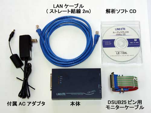 Analyzer AnalyzerAnalysis software CD LAN cable (straight cable, 2 DSUB 25-pin monitor cable Wide-input AC adapter |
|
*2: No connection cable for RS-422/485 is provided. Prepare a cable suitable to the measurement side, or use terminal block adapter LE-5TB (option).
*3: TTL monitor probe pod OP-5M (option) is required.
*4: The parity can be specified as a multi-processor bit.
*5: The number of stop bits can be set to 1.5 only in monitor mode. Transmission data at the time of simulation cannot be set to 1.5 bits.
*6: Arbitrary speed setting to 4 effective digits is possible.
*7: No data recording is possible while in RS-422/485 communication.
*8: No connection cable for the external trigger terminal is provided. Prepare a harness fitting for the terminal connector (HIROSE ELECTRIC’s DF1E-3P-2.5DS), or use three-wire probe cable LE-3LP (option).