Multi Protocol Analyzer
LE-3500XR

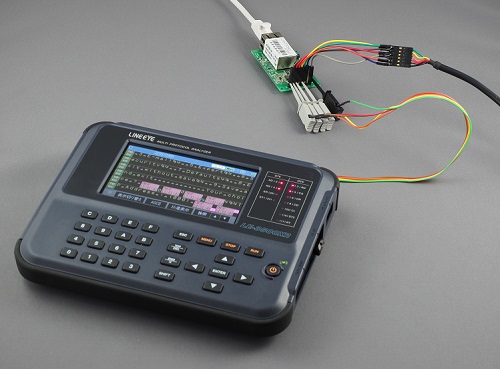
●4.3 inch color touch screen
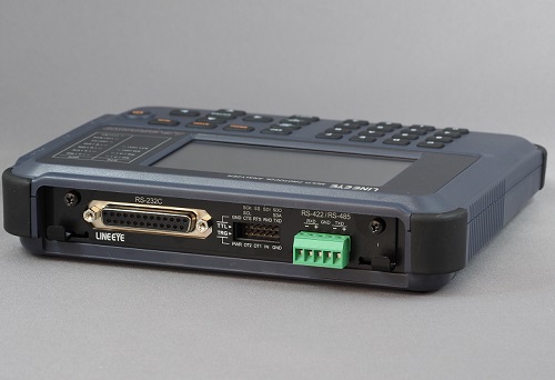
●RS-232C, RS-422/485, TTL (UART/I2C/SPI) as standard
●Supports HDLC/SDLC, Modbus, I2C, and SPI measurement tests as standard
●Supports CAN, CAN FD, LIN, CXPI etc. by optional expansion set
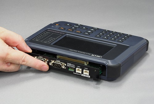
●Supports V.35, X.20/21, and RS-449 by optional expansion board and cable
●Secure long-term recording on USB flash or SD card by AUTO SAVE
●High precision time stamp of hour, minute, second, 10msec
●Logic analyzer analysis and signal voltage measurement
●Supports PC connection and remote control by Wi-Fi
LE-3500XR: Japanese model (with Japanese manual)
LE-3500XR-E: Abroad model (with English manual)
The LE-3500XR is a perfect model of a stand-alone communication protocol analyzer which has a touch panel color display and adopted lithium ion battery while inheriting all the functions of the conventional model LE-3500/LE-3500R which have the monitor function, simulation function, and bit error rate test function necessary for communication analysis test.
Visualization of signal status and error data on the line monitor display is dramatically improved by colorizing the display. With the touch panel and the physical key switch, you can optimize the use of them - for example, swiping of the touch screen for display of a large amount of communication monitor data and key operation for MANUAL simulation mode (in which communication test data are assigned to the keys and transmission/reception test is executed). In addition, many key operations of the conventional model are inherited as shortcut key operations.
The newly designed housing that can built in a lithium-ion battery pack (which can be charged from the micro USB connector) is significantly smaller and lighter than the conventional model, reducing the burden for maintenance of communication device and trouble shooting of communication systems.
LE-3500XR serves for evaluation of RS-232C serial communication, RS-422/RS-485 lines for railway, aviation, and manufacturing lines where reliability is important, and Modbus communication systems. It also serves for a development of embedded firmware of I2C and SPI devices and communication tests of in-vehicle network devices.


| Interface | RS-232C (V. 24) RS-422/485 (RS-530)*1 TTL(1.8V/2.5V/3.3V/5V level) |
|---|---|
| Expansion measurement interface*2 | CAN FD/CAN/CXPI [OP-SB7XC] CAN FD/CAN/LIN [OP-SB7XL] Current loop comm [OP-SB1C] X. 20/21 [OP-SB10N + LE-25Y15] RS-449 [OP-SB10N + LE-25Y37] V. 35 [OP-SB10N + LE-25M34] TTL (USART) [OP-SB5GL] RS-530[OP-SB10N] |
| Expansion firmware*2 | High-speed CC-Link/HDLC/SPI[OP-FW10XR] |
| Standard protocol | ASYNC (Asynchronous), ASYNC-PPP Character synchronous SYNC/BSC Bit synchronous HDLC/SDLC/X. 25 I2C, SPI Modbus BURST*3 |
| Optional protocol | CAN FD, CAN, Devicenet, LIN, Current loop comm |
| Synchronous clock | ST1 (DTE transmission clock), ST2 (DCE transmission clock), RT (DCE reception clock), AR (The synchronous clock extracted from the edge of the transmission and reception data) |
| Capture memory*4 | DDR3-SDRAM 100MB SRAM for automatic saving 512KB |
| Memory usage feature | Use divided in two, protect against accidental erasure, and selection of ring buffer or fixed size buffer are available. |
| Battery back-up | Back up the SRAM and RTC by the built-in lithium battery for about 5 years |
| Baud rate | Full duplex: 2.048Mbps / Half duplex: 3.150Mbps*5 |
| Speed setting range | 50bps to 3.150Mbps*5 |
| Speed setting step and accuracy | Can freely set four effective digits, separately for transmission and reception.(Margin of error: ±0.01% or less) |
| Data format | NRZ, NRZI, FM0, FM1 |
| Data code | ASCII, EBCDIC, JIS, Baudot, Transcode, IPARS, EBCD, EBCDIK, HEX*6 |
| Character framing | ASYNC : Data bit (5,6,7,8) + parity bit (0,1) + stop bit (1,2) Character synchronous : Data bit + parity bit (6 or 8 bits in total) Bit synchronous : Data bit (8 bits) |
| Parity bit | NONE, ODD, EVEN, MARK, SPACE |
| Multi-processor bit | MP (multiprocessor) bit is shown with a special mark. |
| Bit transmission order | LSB first or MSB first (switchable) |
| Polarity inversion | Normal or Inverted (switchable) |
| Error check | Parity (ODD, EVEN, MARK, SPACE), Framing, Break, Abort, Short frame, BCC (LRC, CRC-6, CRC-12, CRC-16, CRC-ITU-T, FCS-16, FCS-32), and BCC transparent mode can be selected. |
| Online monitor function | Communication log is recorded continuously and displayed in the LCD without affecting the communication lines. |
| Idle time display | OFF (no record); Resolusion: 100ms, 10ms, 1ms, or OFF can be selected.; Max 999. 9 sec |
| Time stamp display | Date/Time Units "Day Hour:Minute", "Hour:Minute:Second", "Minute:Second.10msec","Year/Month/Day Hour:Minute", "Month/Day Hour:Minute:Second"," "Day Hour: minute: second.10 ms", or OFF (no recording) can be specified |
| Line status display | Records and displays the wave form of 7 signals, RTS, CTS, DTR, DSR, DCD, RI, TRG (external trigger input) along with the transmission / reception data. |
| Address filter | Records only frames of the specified address. (only when HDLC / SDLC / X.25) |
| Data display and operations | Pause in capture, scroll, paging, jump to the specified screen. |
| Bit shift display | Entire frame can be shifted to the right or left in 1 bit increments. |
| Protocol translation display | SDLC (modulo 8/128), ITU-T X.25 (modulo 8/128), LAPD, PPP, BSC, I2C, Modbus |
| Line status LED | Two color LEDs of SD, RD, RS(RTS), CS(CTS), ER(DTR), DR(DSR), CD(DCD), CI(RI), ST1(TXC1), ST2(TXC2), RT(RXC). |
| RS-232C | Logic ON (red) , logic OFF (green) , no connection NC (light off) |
| Other I/F | Logic ON (red) , logic OFF or no connection NC (light off) |
| Interval timer | 2kinds; Max. count: 999999 (Resolution: 1ms ,10ms ,100ms) |
| General-purpose counter | 2kinds; Max. count: 999999 |
| Data counter | For SD and RD (1 each): Max. count: 4294967295 |
| Trigger function | Up to four pairs of trigger conditions and actions can be specified. Sequential actions, which validate another condition after one condition is satisfied, are possible. |
| condition | Communication error (Parity, MP, framing, BCC, break, abort, short frame can be specified individually.), communication data string up to 8 characters (don't care and bit mask available), idle time more than the specified duration, match time/counter value, logic status of interface signal line and extarnal trigger input |
| action | Stops measurement/test (number of offsets until a stop can be set), validates trigger conditions, controls timer (start/stop/restart), controls counter (count/clear), activates buzzer, saves monitor data on a memory card, sends the specified character string (during manual simulation), and sends pulse output to external trigger terminal OT2. |
| External trigger output | Sends pulse output to external trigger terminal OT1 when all conditions are satisfied. Sends pulse output to external trigger terminal OT2 when the trigger action is set so. |
| Data search function | Retrieves the data with specific condition from capture memory. |
| condition | Communication error (parity, MP, framing, BCC, break, abort, short frame can be specified individually), communication data string up to 8 characters (don't care and bit mask available), idle time more than the specified duration, specified time stamp, time stamp of the specified time (the time range can be specified), and trigger matching data |
| action | Shows the match data at the top or enumeration display (selectable) |
| Mark jump | You can add marks (up to 5 points) to the data in the capture memory and jump to the marked position. |
| Monitor conditions auto setting | Measurement conditions such as protocol, transmission speed, (max. 460.8Kbps), framing, data code, synchronous character and BCC check can be automarically set.*7 |
| Auto run/stop function | It can automatically start and finish measurement at the specified time at the selected repeating cycle (monthly, daily, hourly). |
| Power ON auto run function | It can automatically start measurement when power is turned ON. |
| Auto save function | Automatically saves the monitored data in the capture memory and saves as communications log file in a SD card or USB flash memory. Restart mode and Append mode (which are ring save operation) and Max mode (in which the measurement stops at the specified capacity.) can be selected. |
| File size | BUF (capture memory size) , 1MB , 2MB , 4MB , 8MB , 16MB, 32MB |
| MAX. files | 1024 |
| Delay time function | Measures and displays the interval of change in the interface signal line. (current/min/max/average, resolution: 0. 1ms) |
| Signal voltage measurement function | Measures and displays the value of voltage amplitude: |
| Statistical analysis function | Takes statistics for 1 to 240 minutes (1 min unit) and displays graphs of transmission/reception data, number of frames, and satisfied trigger condition count. |
| Logic analyzer function | Measures the logical change of the interface signal in the sampling clock period, and displays its wave. |
| Sampling clock | 1KHz to 20MHz (14 steps) |
| Sampling memory | Max 4096 |
| Trigger condition | Logical status match between interface signal line and external signal. Match of the specified trigger conditions of ONLINE monitor functions |
| Trigger position | Before, center, after |
| Trigger pass count | You can specify the number of times (0 to 9999) to pass (ignore) the trigger condition match |
| Zoom in/out | ×10, ×5, ×2, ×1, ×1/2, ×1/4, ×1/8, ×1/16, ×1/32, ×1/64 |
| Other functions | Time measurement between the cursors, signal line exchange, signal status search |
| Bit error rate test | Conforming to ITU-T G.821 it measures line quality such as bit error rate and block error rate*8. |
| Communication mode | Synchronous (SYNC) or Asynchronous (ASYNC) can be selected. RTS/CTS flow control is available. |
| Measurement speed | 50bps to 3.150Mbps*5, freely set by four effective digits |
| Measurement mode | Continuous measurememt, specifies the number of receiving bit, specifies the time to measure, repeatedly measurement at the unit of 1 - 1440 min |
| Test pattern | 26-1, 29-1, 211-1, MARK, SPACE, ALT, DBL-ALT, 3in24, 1in16, 1in8, 1in4 |
| Error bit insertion | Inserts 1-bit or 5-bit error in test pattern by key operation. |
| Measurement range | It is able to measure the parameter of the ITU-T advice G.821. Effective received bit (0 to 9999999sec), bit errors (0 to 9999999 to 9.99E9), bit error rate(0 to 9. 99E-9 to 1), block errors (0 to 9999999 to 9.99E9), block error rate (0 to 9.99E-9 to 1), Savail(available measurement time: 0 to 9999999sec), loss count (synch loss: 0 to 9999), error duration (0 to 9999999sec), %EFS (normal operation rate: 0. 000 to 100. 000%) |
| Simulation function | Transmission/reception test of arbitrary data in DTE or DCE mode (pin assingnment can be switched) is avaialble. |
| Transmit data entry | Transmit data entry: Register 160 kinds of transmission data tables (10 Groups x 16, total 16K data) |
| Error data entry | A part of transmission data can be registerd as error data such as parity error. |
| Line auto control | Auto (Controls transmission timing with RS(RTS), CS(CTS), ER(DTR), CD(DCD) signal lines automatically in 1 ms resolution) or manual control (key operation) can be selected. |
| Transmit driver control | During simulation, if RS-422/485 driver IC is / always activated / automatically activated before and after data transmission / activated in conjunction with [SHIFT] + [F] operation are selectable. |
| MANUAL mode | Sends the data assigned to operation keys each time a key is pressed, while checking communications status on the display. Can be used together with the trigger function |
| FLOW mode | Simulates the X-on /X-off control data and flow control procedures of RTS/CTS control line. (To be sender or receiver is selectable).*9 |
| ECHO mode | Returns reception data in frames (buffer echo), in bytes (character echo), or by looping back (loopback echo). |
| POLLING mode | Simulates polling communications procedures. (To be slave or master is selectable.) |
| BUFFER mode | Reproduces transmission of selected data (SD or RD) captured in memory by monitor function. |
| PROGRAM mode | Creates a simulation program (Max. type: 4, Max steps: 512) using the dedicated commands (38 types) to test the communication procedure. |
| File management function | Measurement data and condition can be saved in a SD card or USB flash. And the format of the data/condition can be used in a PC. |
| File types | Measurement data (.DT), all measurement conditions (.SU), trigger save data (TGSAVEnn.DT), and auto save data (#nnnnnnn.DT) |
| File controls | Normal file display, file display by specified type/created date basis, save, load, delete, delete all. |
| Supported storage device | 2G to 32G byte SD/SDHC card (only the optional SD card sold by LINEEYE are supported.) or a USB flash memory up to 32Gbyte |
| Remote Control | PC link software "LE-PC300R"(light edition) is attached*10 The Library to control the analyzer is available. |
| Print out*11 | Measurement data can be printed continuously in various formats, and display images can be printed as hard copies. |
| LCD | 4.3 inch TFT color display (480 x 272 dot) |
| Touch panel | Capacitive touch panel |
| SD card slot | Standard size for SD/SDHC memory card. Compatible with the standard of SD association. |
| USB2.0 device port | Micro B-connector supports High speed transfer. Can be used for PC connection [LE-PC300R], bus power supply, and firmware upgrade. |
| USB2.0 host port | Standard A-connector supports High speed transfer. Can be used for USB flash memory. |
| Wi-Fi Connection | IEEE 802.11 b/g/n*12 Frequency range: 2400MHz-2483.5MHz Transmission power: +20dBm(802.11b), +17dBm(802.11g), +14dBm(802.11n) Used for PC connection by LE-PC300R |
| Power supply | USB bus power DC5V 1A Attached USB charger input:AC100 to 240V, 50/60Hz |
| Built-in battery | Lithium-ion secondary battery (Model: P-26LS1) |
| Battery operating time*13 | About 7 hours |
| Battery charging time | Quick charge: About 3.5 hours Normal charge: About 6 hours |
| Temperature range | In operation : 0 to 40 degree Celsius, In storage : -10 to 50 degree Celsius |
| Humidity range | 85% (RH) max. |
| Standard | CE(Class A) |
| Dimension, mass | 190 ( W ) x 153 ( D ) x 38 ( H ) mm, About 550g |
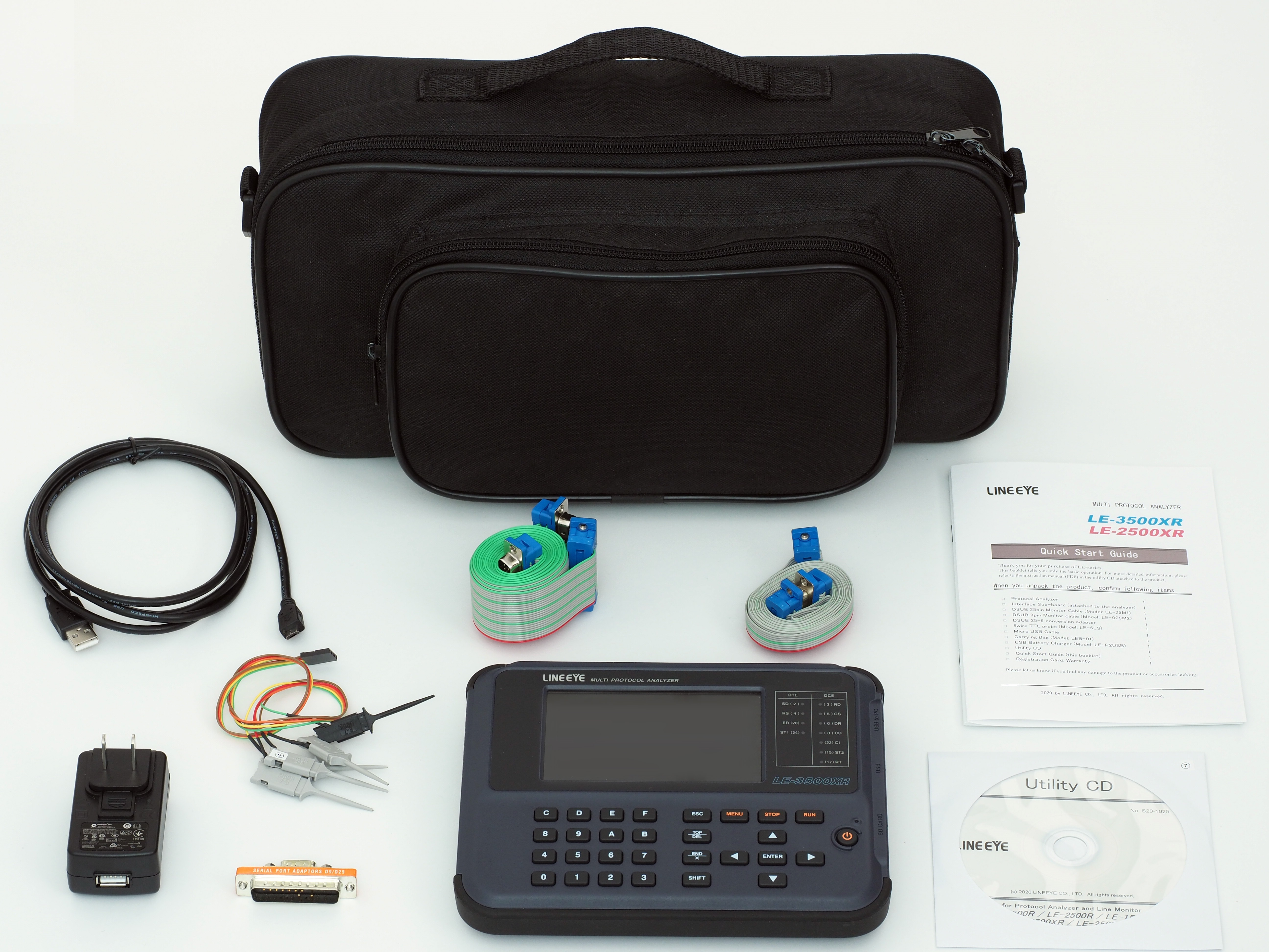
| Accessories | Monitor cable for DSUB 25-pin (LE-25M1), Monitor cable for DSUB 9-pin (LE-009M2), DSUB25pin-9pin conversion adapter, 5 wires TTL prove cable (LE-5LS), micro USB cable, USB charger (LE-P2USB), carrying bag (LEB-01), Utility CD, quick start guide, and warranty |
<Standard Accessories>
*1: To monitor control line, expansion board “OP-SB10N” (which has RS-530 port) is needed.
*2: To use the function, the optional accessories described in the brackets are required.
*3: This mode is used to capture all data in synchronization with clock edges.
*4: Transmission/reception data, idle time, time stamp, and line status items consume 4 bytes of memory at each capture.
*5: Firmware Ver.1.04 or later. 1 Mbps for I2C
*6: JIS (7bit data), EBCD, and Baudot are displayed in different characters depending on the shift-out (SO) and shift-in (SI) characters.
*7: This function supports only ASYNC, SYNC/BSC, HDLC/SDLC. Correct auto settings are impossible if the amount of communications data is small or communications data includes a large number of errors.
*8: Only ASYNC mode and SYNC mode are available.
*9: Only ASYNC is available.
*10: This is the light edition of optional product “LE-PC300R” (with some limitation for its functions).
*11: A dedicated printer (SM4-31W) is required.
*12: Wi-Fi function is available only in Japan, USA, Canada, and EU nations where the product is needed to be compliant with RE directive (2014/53/EU). The Wi-Fi function of this product is set to invalid depending on the country where it is shipped. Please contact LINEEYE for the detail.
*13: The battery operating time was measured under LINEEYE's measurement conditions with the LCD backlight turned OFF.