LE-PC300G (PC Link Software)
Outline
| LE-PC300G is Windows® software which
enables a PC to control LINE EYE protocol analyzers from
remote in order to use measurement data of those analyzers on
a PC. It is compatible with the following analyzers: LE-3500, LE-2500, LE-1500, LE-7200, LE-3200, LE-2200 and LE-1200. |
 |
Features


Enables simultaneous control of multiple analyzers from a PC
| The LE-PC300G supports serial connections through the COM port, USB connections, and LAN connections with the SI-60 (sold separately) used, and allows remote simultaneous measurement with a number of analyzers connected together. Furthermore, the LE-PC300G makes it possible to display measurement data saved on memory cards and/or convert the measurement data. |
 |
 |
|
| *1: No USB cable is provided. Prepare an appropriate USB cable if data is transferred over the USB. In the case of serial connections, use the LE2-8V auxiliary cable provided to the analyzer. *2: An interface to read CF card data is required on the PC side. |
*1: SI-60 is a LAN-serial converter supported by LE-PC300G. Target analyzer is identified by specifying IP address of SI-60 on the remote setting window of LE-PC300G. *2: Optional AUX cable for DSUB 25-pin (LE2-8C). Set the DTE/DCE switch of SI-60 to DTE. |
Key emulation
The key emulation function reproduces the display and operation of analyzers on your PC. It allows you to perform remote control as if you operated your analyzer from a PC.
Remote monitor
The remote monitor function allows to capture log data from analyzer operating and displays the data on the PC's screen recording it on its hard disk. The fixed buffer and ring buffer mode are available. The former stops recording when the specified data size is reached, and the latter records data endlessly within the limit of the specified size.
Displays on the PC screen in various ways.
This function allows you to switch the display mode: raw data display, protocol translation display, and logic analyzer waveform display.
Raw data display
HDLC translation display mode
Logic anlayzer display mode
Converts the stored data to a text or CSV format all together
This function allows you to convert into a text or CSV format the data stored by the remote monitor function or stored in a memory card by an analyzer all together.
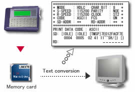
Converts data stored on a memory card to the text/CSV format.
Changes the system language automatically (Japanese/English)
The system language alternates automatically between English and Japanese according to that of OS. This facilitates introduction of the software to development bases outside Japan.
English
Japanese
Specifications
| Applicable analyzers | LE-3500, LE-2500, LE-1500, LE-7200, LE-3200, LE-2200, LE-1200 | |
|---|---|---|
| Analyzer connection | Serial, USB (for full-speed transfer), and LAN (with SI-60 unit sold separately) | |
| NO. of analyzers to be connected | Multiple analyzers can be connected and controlled simultaneously. (No. of connectable analyzers depends on the performance of PC.) | |
| Key emulation function | Presents the analyzer's display on the PC screen to anable control in a manner as if operating the analyzer. | |
| Measurement condition setting | Measurement conditions (communications parameters, trigger and simulation data) can be input and edited on the dedicated window on the PC screen. | |
| Remote monitor function | Starts/stops measurement with a analyzer, displays the measurement data on the PC screen, and records data continuously.*1 | |
| Recording mode | Fixed buffer mode (Records data up to the specified size) or ring buffer mode (Records data endlessly while leaving the latest data of the specified size) can be selected. | |
| Recoding capacity | Max. 16 GB. Can be specified up to 2,000 files in the unit of 1/2/4/8 MB data file. | |
| Display modes | Selectable among raw data, protocol translation and logic analyzer waveform. | |
| Raw data | Displays communications data accompanied by idle time, time stamp, and line status.Character code (10 kinds) and character size (small/ medium /large) can be changed. | |
| Protocol translation | Translates and displays SDLC, X.25 and LAPD protocols. (Target protocols planned to be increased.) | |
| Logic analyzer waveform | Enlarges and reduces waveform, measures time between cursors, and rearranges signals. | |
| Display area | Display window size can be changed. | |
| Character codes | ASCII, EBCDIC, JIS7, JIS8, Baudot, Transcode, IPARS, EBCD, EBCDIK, HEX (in hexadecimal including error codes) | |
| Search function | Finds and displays the data that matches the search key. | |
| Search key | Specified data string of max. 8 characters (don't care and bit mask can also be specified), idle time beyond a specified duration, specific time stamp (don't care can also be specified), error (parity, framing, BCC, break/abort, short frame: individual error type can be specified) external trigger matching data | |
| Text-CSV conversion function | Specified number of recorded files can be converted to text or CSV format all together. | |
| Bitmap conversioh function | Analyzer's display shown by any emulation can be saved to bitmap files. | |
| System requirements | PC | PC / AT compatible CPU: Pentium3 1GHz or fasterRAM: 256 MB or more (recommended)HDD: 5 MB + free bytes on the measurement data area |
| OS | Windows® XP/Vista/7/8 | |
| Composition | CD (software) x 1, instruction manual x 1 | |
| USB connection | Max. 700Kbps | |
|---|---|---|
| Serial port direct (115.2Kbps connection) |
Max. 20Kbps | This is the max speed of actual communications. For example, the speed of your target device is 1Mbps, and it communicates 2Kbyte/s. The actual communication speed of this target device is 20Kbps. |
| Via SI-60 (230.4Kbps connection) |
Max. 40Kbps | |