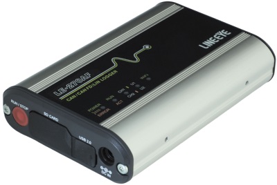
PC-connectable protocol analyzer / Data logger
LE-270AF
●2-way operation of PC-connected protocol analyzer / logger
●2-channel measurement by combination of CAN/CAN FD and LIN
●Remote measurement of multiple analyzers with one PC
●The measurement log in SD card can be checked from PC via Wi-Fi without stopping measurement
●Records 4 external signals of ±16V or 0V to 32V along with communication data
●Test transmission function to send repeatedly pre-registered communication data strings by selecting it on PC
●Communication transceiver and analog measurement circuit are electrically isolated from the measurement recording circuit section connected to a PC
●Optimal backup control during momentary power outage protects files from power outages while accessing the SD card
●Robust design to withstand use in harsh field environments
The LE-270AF is a small and lightweight CAN/CAN-FD/LIN communication data logger capable of measuring analog voltages up to 32V. It can be used in two modes: logger mode, which allows continuous recording of measurement logs to a large-capacity SD card by itself, and remote mode, which connects to a personal computer (hereinafter referred to as PC) via Wi-Fi or USB as a CAN/CAN-FD/LIN communication analyzer and displays measurement data of communication, positioning, acceleration, and analog voltage in real-time on the PC. In remote mode, multiple analyzers can be remotely measured from one PC and continuously recorded on the PC's HDD, etc., and you can compare and analyze multiple communication lines. It also has a test transmission function that allows pre-registered test communication data to be selected on the PC and repeatedly transmitted, which is useful when developing communication devices. It is resistant to momentary power outages and can be used where there are water droplets. As it consumes low power it can be widely used for installation in test vehicles and integration into inspection lines.
The differences with LE-270AR are as follows.
| Model number | LE-270AR | LE-270AF |
|---|---|---|
| Supported protocols | CAN/DeviceNet/LIN | CAN/CAN FD/DeviceNet/LIN |
| SD card Maximum capacity |
16GB | 32GB |
| Remote measurement of multiple analyzers | No | Yes |
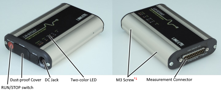

■ 2Two-color LED

Lights of LED stand for following:
| POWER/ERROR | Indicate the operating status of analyzer. |
|---|---|
| RUN/ACT | Indicate that analyzer is measuring or accessing to the SD card |
| CH1/CH2 | Indicate the logic status of CH1/CH2. |
| U1/U2 | Able to light the U1(green)/ U2(red) by trigger action. |
| WiFi* | Indicates Wi-Fi connection |
■ Pin Assignment of Measurement Connector (DSUB25pin)
| 1 | BATTERY | 14 | TRG IN |
|---|---|---|---|
| 2 | - | 15 | CAN1 High |
| 3 | - | 16 | CAN1 Low |
| 4 | GND | 17 | TRG OUT 2 |
| 5 | - | 18 | TRG OUT 1 |
| 6 | - | 19 | CAN2 High |
| 7 | GND | 20 | - |
| 8 | - | 21 | CAN2 Low |
| 9 | EXT IN 1 | 22 | GND |
| 10 | EXT IN 2 | 23 | LIN1 |
| 11 | EXT IN 3 | 24 | LIN2 |
| 12 | EXT IN 4 | 25 | - |
| 13 | - | - | - |
When in logger mode the unit can be powered from 1pin (BATTERY). (Power supply from pin 1 consumes about 30mA even when the power is shut down. If you want to reduce current consumption, supply power from the DC jack.)
Two Types of Operation Based on Usage Situation.
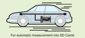
■ Easy-to-Operate Data Logger Mode.
Simply press a switch on the panel to start logging the measurement data into an SD card. No complicated configuration operation is required in the field, since the measurement conditions can be stored in advance in a configuration file in the SD card. The measured log file can be transferred from the SD card to a PC for analysis.
It is useful in the situation of:
- PC usage is not allowed.
- Dusty places (PC cannot be used).
- Need to record data for more than one month.
- Cannot operate the analyzer well.
- There are space limitations.
< Logger Mode >
■ Remote Mode Capable of Real-time Monitor Display.
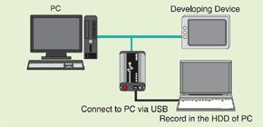
When PC-connected via USB, it operates as a PC-connectable analyzer that is capable of changing the settings of measurement conditions, displaying measurement data in real time and recording continuously to a HDD from a PC. It can also display a communication log file acquired in the logger mode and create a measurement configuration file for logger mode.
< Remote Mode >
Control multiple analyzers with one PC
You can control multiple analyzers simultaneously and analyze communication data from multiple locations where the analyzers are. You can display the measurement windows for each analyzer on a single computer screen to check the communication status.

Simultaneous measurement of CAN/CAN FD/LIN/analog signals
t can simultaneously measure two channels of CAN/CAN FD/LIN communication lines and four external signal states (analog voltage value/digital logic). Each communication monitor circuit is equipped with a CAN transceiver and a LIN transceiver, and each transceiver can be selected from the software depending on the test situation. In addition, online mode and analog mode are available depending on whether you want to measure communication data or external signal state.
■ ON-LINE Mode
The analyzer records status of external signal at the time of recording CAN/LIN data. It can display time stamp, LIN SynchBreak, LIN SynchField, ID, Frame type, status, data, CRC/checksum, external signals, trigger marks and so on.
| ST | Meaning |
|---|---|
| G | Normal Frame |
| B | Synch Break error of LIN (When Dominant is 10bit) |
| S | Synch Field error of LIN (Other than 0x55) |
| P | Parity error of LIN |
| L | Data length error of LIN ("ID"is set in "Frame End" setting ) |
| R | When the data of the Response of LIN is less than 1byte |
| C | CRC error of CAN/CAN FD / Checksum error of LIN |
| A | ACK error ofCAN/CAN FD |
| E | Error frame of CAN/CAN FD |
| F | Form Error of CAN/CAN FD (When CRC or ACK delimiter is 0) |
Data Monitor (Normal Display)
After the measurement, it is possible to scroll and search data for further analysis on the Data Monitor Display.
< Retrieval Configuration >

It is possible to search, search for and count measurement data that meets specified conditions.
In the example screen, LIN frames with a break dominant period of 10 bits and LIN frames with parity errors are searched for and displayed.
Various CAN/CAN FD and LIN errors are reliably caught and can be checked in the St column.
< Data Monitor Display (with error marks) >

Watch Data Display
Watch Data Display displays specified ID frame at appointed place at real time.
< Watch Data Display ID Configuration >

Also, if you check Auto, frames flowing on the line will be automatically collected and displayed in the order of the ID observed by the analyzer, which is useful when the ID is unknown.
< Watch Data Display >

Timer/ Counter Display
Timer/ Counter display shows the total received frames and occurrence number of specific event.
Timer 0-3 and Counter 0-3 can be used as trigger conditions.
(Example of Using Timer)
Measure time between specific events, such as time between receiving external signal and receiving specific data.
(Example of Using Counter)
Count number of occurrences of specific events, such as CRC errors of CAN.
< Timer/ Counter Display >

■ Wide range analog measurement
It can measure the status of four external analog signals of ±16V or 0 to 32V at a specified sampling period and display the analog waveform, so it can be used like a four-input analog data logger.
< Analog Mode Configuration >

< Analog Waveform Display >

It is possible to select the range of display from ±1V, ±2V, ±5V, ±10V, ±16V, and display each signal.
< Data Monitor Display >

Analog mode records not only the latest data but also the continuous data from the last sampling. It is able to know how data has changed as time passes.
< Example of using data in the spread sheet >

It is able to convert Analog data into text/CSV format
Long Hour Recording
Log files are saved at the specified file size and number of files, continuously as a ring buffer. Also, measurement can stop when the specified number of files has been reached. It is useful for detecting any hindrance in the line.
[Estimated recording time for a specified capacity of 1.8 GB (4 MB x 450 files)]
・When 1 CAN frame (8 bytes) is transmitted at 1 ms intervals at 125 kbps
Approximately 15 hours and 40 minutes
・When 1 CAN-FD frame (64 bytes) is transmitted at 0.1 ms intervals at 1 Mbps
Approximately 30 minutes
Communication frames of 8 bytes or less: 32 bytes
Communication frames of 9 to 36 bytes: 64 bytes
Communication frames of 37 to 64 bytes: 96 bytes
< Buffer Configuration (Remote Mode) >

< Buffer Configuration (Logger Mode) >

Perform Analysis at any Communication Rate.
General communication rates via CAN and LIN have been preset. However, it can be configured to any communication rate. For CAN, it is capable of fine-adjusting the bit sampling timing.
< LIN Configuration >

LIN baud rate can be selected from 2400bps, 9600bps, 19200bps, or set any speed of four effective digits up to 20Kbps.
< CAN Configuration >

You can select or directly enter the communication speed (125K to 1000K) for CAN and CAN FD. You can also select or directly enter the data phase communication speed (1000K to 5000K) for CAN FD.
[CAN bit sampling point]
The analyzer can specify the sampling position of 1 bit at the 60% to 90% position.
LIN Frame Configuration
If users know the LIN specifications, it is able to start measuring by specifying the ID frame and checksum type. Even though the users do not know the LIN specification, it is possible to end frames by specifying time.
< Frame Setting by Each ID >

< Frame End Time Setting >

Efficient Analysis Using the Filter Function
It is capable of effectively monitoring by selecting target node IDs. Able to set following filters; the Acceptance filter which specifies target ID in bit, the Pass filter (up to 8) which targets the specific ID, and Cut filter which removes the specific ID from the target ID.
< Filter setting >


You can select conditions such as acceptance, pass, cut, acceptance & pass & cut, etc.

IDs which passed through the acceptance filter can be filtered in the order of the pass filter and the cut filter.
In this example, ID: 101, 102, 103, 104, 184 to 18F, and 1F4 to 1FF will be monitored.
Trigger function for finding specific events
Powerful trigger function stops measuring automatically when receiving errors or fining specific events. Also, it it able to count the events which satisfies the trigger conditions, output trigger signals, and send error signals such as lighting LEDs etc.

Select trigger number to activate the trigger conditions.

If receiving 14h, Foh, W0(data of lower bit 0) and *(specified data) specific data, lights the LED of U1.

If receiving checksum error frames, add one in Counter2.
Schedule Measurement, Low Power Consumption.
Real Time Clock (RTC) backed up by the battery of the analyzer makes it possible to specify the starting and ending times of the measurement. After the measurement, it turns off the power automatically and saves on power consumption. Power-On-Run function starts measurement when the power is supplied from the test devices, and Auto-Power-Off function ends measurement when there is no power supplied from the test devices. This minimizes battery usage of in-vehicle equipment.
< Auto RUN/ STOP setting >

Example 1
Measure while the factory runs operation from 9:00 to 17:30.
< Configuration of Example1 >

| Saving Mode | Append |
|---|---|
| Max Files | 450 |
| File Size | 4M |
| Mode | Daily |
| Run Time | 9:00 |
| Stop Time | 17:30 |
| Power On Run | off |
LED of the analyzer will start blinking at 8:59 and be ready for measurement. It will start measuring at 9:00 and record data in the SD card for 450 files (4M each) as a ring buffer. It will stop measuring at 17:30 and turn off the power automatically to save on power consumption.
Example 2
Equipment communicates with other equipment while it receives power from a power supply randomly.
< Configuration of Example2 >

| Saving Mode | Append |
|---|---|
| Max Files | 500 |
| File Size | 1M |
| Mode | Daily |
| Run Time | non |
| Stop Time | non |
| Power On Run | on (safety start) |
In this care, it is necessary to prove power to the analzyer from the same power supply for the equipment. Safety start will start measuring approximately 40 seconds (LED will be blinking) after powering on the analyzer for charging the capacitor for back-up data. Communication logs will be saved in the SD card for 500 files (1M each) endlessly. The analzyer will stop measuring when the power is not supplied for more than 1 second after saving data in the SD card.
Mass Data is Analyzed Efficiently
One or more communication log files can be converted collectively into text or CSV format so that communication data can be used effectively in a word processor and/or spreadsheet software.
< Text Conversion >

[Example of text conversion data]

<Example of using CSV conversion data>

Manual simulation function that can repeatedly send CAN/LIN data
■ For CAN/CAN FD
One-touch transmission of CAN/CAN FD standard data and extended format data frames and CAN remote frames preregistered in the data table is available. Part of the data in the frame can be specified as sweep data, and the sweep data can be sent while changing sequentially from the initial value to the third target value at a specified time. This function is very useful when checking how CAN or DeviceNet devices behave in response to changes in communication data.
■ For LIN
This unit can simulate a LIN master or slave.
Up to 16 types of headers and responses to be sent can be pre-registered. The response space (space between the header and response) and byte space (space between response data) can be set in the range of 0 to 99 bits.
In master mode, the contents of the data table can be repeatedly sent in the order set in the schedule table, or a schedule number can be specified by key operation and sent. Parity error, number of bits in the BREAK field (13 bits when not specified), and SYNC field abnormal data (normal 55h when not specified) can be set for each schedule number, making it easy to perform operation tests when a communication abnormality occurs. In slave mode, the contents of the data table with the ID that matches the request from the master are sent. Also, the WakeUP signal (80h) can be sent at any time during the simulation.
One-touch transmission of CAN/CAN FD standard data and extended format data frames and CAN remote frames preregistered in the data table is available. Part of the data in the frame can be specified as sweep data, and the sweep data can be sent while changing sequentially from the initial value to the third target value at a specified time. This function is very useful when checking how CAN or DeviceNet devices behave in response to changes in communication data.
This unit can simulate a LIN master or slave.
Up to 16 types of headers and responses to be sent can be pre-registered. The response space (space between the header and response) and byte space (space between response data) can be set in the range of 0 to 99 bits.
In master mode, the contents of the data table can be repeatedly sent in the order set in the schedule table, or a schedule number can be specified by key operation and sent. Parity error, number of bits in the BREAK field (13 bits when not specified), and SYNC field abnormal data (normal 55h when not specified) can be set for each schedule number, making it easy to perform operation tests when a communication abnormality occurs. In slave mode, the contents of the data table with the ID that matches the request from the master are sent. Also, the WakeUP signal (80h) can be sent at any time during the simulation.
Can be used in Various Situation
■ Protects SD Cards from Corruption due to any Sudden Power Failure. [Acquired Patent in Japan]
A newly developed Instant Power Failure Prevention circuit with a Super Capacitor protects important communication log files stored in the SD cards. It protects data in the SD card in case it occurs the power failure during recording to the SD card. The analzyer is useful for on-board tests where power supply is likely to be unstable.
■ Supports wide input DC power
Supports DC8V to DC32V. It is able to supply power from optional AC adapter and the battery of vehicle. An optional adapter for boosting voltage of external battery is also available.
[ Usage of external battery ]

■ Small and Robust Housing Suitable for Severe On-board Testing
The palm-sized robust unit can be used between ?20 to +60°C. It can be installed even within a limited vehicle test space. The consumption current is as low as 100mA at DC12V input. With the dust-proof cover closed, and the DC cable and optional water-proof DSUB cable connected, it can be used in places where it may be exposed to dust and drip.
< Dust-proof covers >

< DIN Rail Installation Example >

■ Automatically Switches between Japanese and English
The system language alternates automatically between English and Japanese according to that of OS. This facilitates introduction of the software to development bases outside Japan.
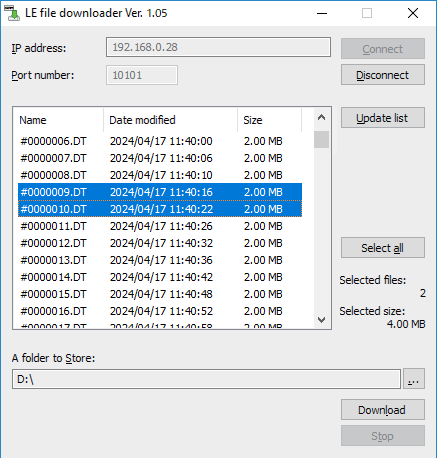
■Read log files over Wi-Fi without stopping logger operation
By connecting it to your PC by Wi-Fi, you can check the log files recorded on the SD card without stopping measurement in logger mode.
You can use the included utility software lefiledownload to list log files and download the specified file.
