CAN/CAN FD/LIN
PC-connectable protocol analyzer / Data logger
PC-connectable protocol analyzer / Data logger
LE-270GR
●2-way operation of PC-connected protocol analyzer / logger
●2-channel measurement by combination of CAN and LIN
●Simultaneous recording of GPS, acceleration, and external signal measurements with CAN/LIN data
●Galvanic isolation between CAN/LIN transceiver and analog measurement circuit
●pass / cut filter and powerful trigger function makes the analysis more efficient
●Can check the log file without stopping the logging
●Robust design to withstand use in harsh field environments
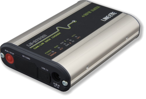
LE-270GR is a Communication Data Logger, which has acceleration sensor and a connector for GPS antenna. It has logger mode with which you can records CAN/LIN communication logs in the SD/SDHC card for long hours and remote mode with which you can monitor data or GPS data on the PC at real time by connecting the analyzer with PC. It also has simulation mode with which you can repeatedly transmit CAN/LIN data which is registered in advance and selected on PC. It has galvanic-isolated two CAN transceivers and two LIN transceivers. Thus you can measure 2 channels of CAN/LIN communication lines and can simultaneously register GPS positioning data, acceleration data, and voltage data of 4 external signals.
Its power failure protection, waterproof, and low power consumption widens the usage of analyzer such as in the automation factories and other production factories.
| Interface | CAN: Comfort to ISO11898 standard, TJA1050. |
|
|---|---|---|
| Signal Isolation | 1KV galvanic isolation Between CAN/LIN/external signal and measurement processing unit (USB, SD, DC-IN) |
|
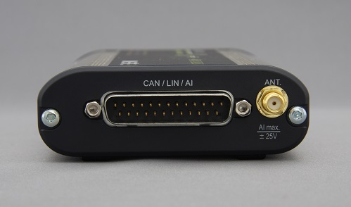
| Connector | DSUB 25 pin male connector #4-40UNC | |
| Number of Channels | 2 channels of CAN or LIN, or 1 CAN and 1 LIN | |
| Protocol | CAN, Device Net, LIN (Rev1.1, 1.2, 1.3, 2.0, 2.1) | |
| Baud Rate | CAN: 125Kbps-1Mbps LIN: 400bps-26Kbps (arbitrary) | |
| CAN Monitor | Standard/ Expansion format. Support bit timing settings. | |
| LIN Monitor | Frame breaking is possible according to the data length of each ID or specified idle time. | |
| Error Check | Break:(LIN), Sync:(LIN), Parity:(LIN), Checksum:(CAN/LIN), Framing:(LIN) | |
| Memory | PC: Max 32G byte on the HDD, PC-less: Capacity of the SD card (Specify the file size as 128K /1M / 2M/ 4M / 8M / 16M / 32M byte) |
|
| Recording Type | Ring Buffer (continuous) mode, Fixed Buffer (full stop) mode | |
| Mode | Remote mode (with PC); Data Logger mode (PC-less) | |
Measurement test mode |
Online mode, Analog mode, Manual mode (Simulation) | |
| Measurement start/stop | Control from PC, Start/Stop switch, Auto-Power run, Specify date and time. | |
| Time Stamp | “Hr:Min:Sec”, “Min:Sec:x1ms”, 9 digits: “100μs”, “10μs”, “1μs” (selectable)*1 | |
| Filter | Record specific frames using Bit-mask ID, Bus ID (up to 8), Cut ID (up to 8). | |
| Display on PC | Real-time display, Watch data display(display specified data of each ID) | |
| Trigger | Condition | Data string up to 8 characters, specified remote frame (CAN), frame error (LIN), timer and counter, logic status of external signal, external trigger input. |
| Action | Stop measurement (offset can be set), validates/invalidates trigger condition, control timer/counter, turn on/off the light of user-defined LED, output external signals, output trigger signals, Transmits CAN data (when in manual mode). | |
| Retrieval function on PC | Trigger matched data, Error (Break, Sync, Parity, Checksum, Framing), Data: Specified ID (don’t care available), Data string (Up to 8 characters; don’t care and bit mask available), CAN Remote Data: Specified ID (don’t care available), Specified Time stamp, External signal | |
| External Signal Input | Digital/Analog 4 channels Recording: At the time of receiving signals, or specified sampling cycle (1ms - 10min, 13steps) Digital VIH 2V (Min.), VIL 0.5V (Max.) Analog Range: -16V to +16V, Accuracy: ±0.5%FS, A/D conversion: 15Ksps, Resolution: 10bit |
|
| Acceleration data | Registers acceleration data of X/Y/Z axes. 3 axes acceleration sensor (equivalent to KX022-1020-FR) is built-in. | |
| GPS positioning data | Registers and displays latitude, longitude, and above sea level. SMA (female) connector for active GPS antenna is equipped. | |
| Conversion | Convert data into Text, CSV, or KML format and save. OBD translation is supported. | |
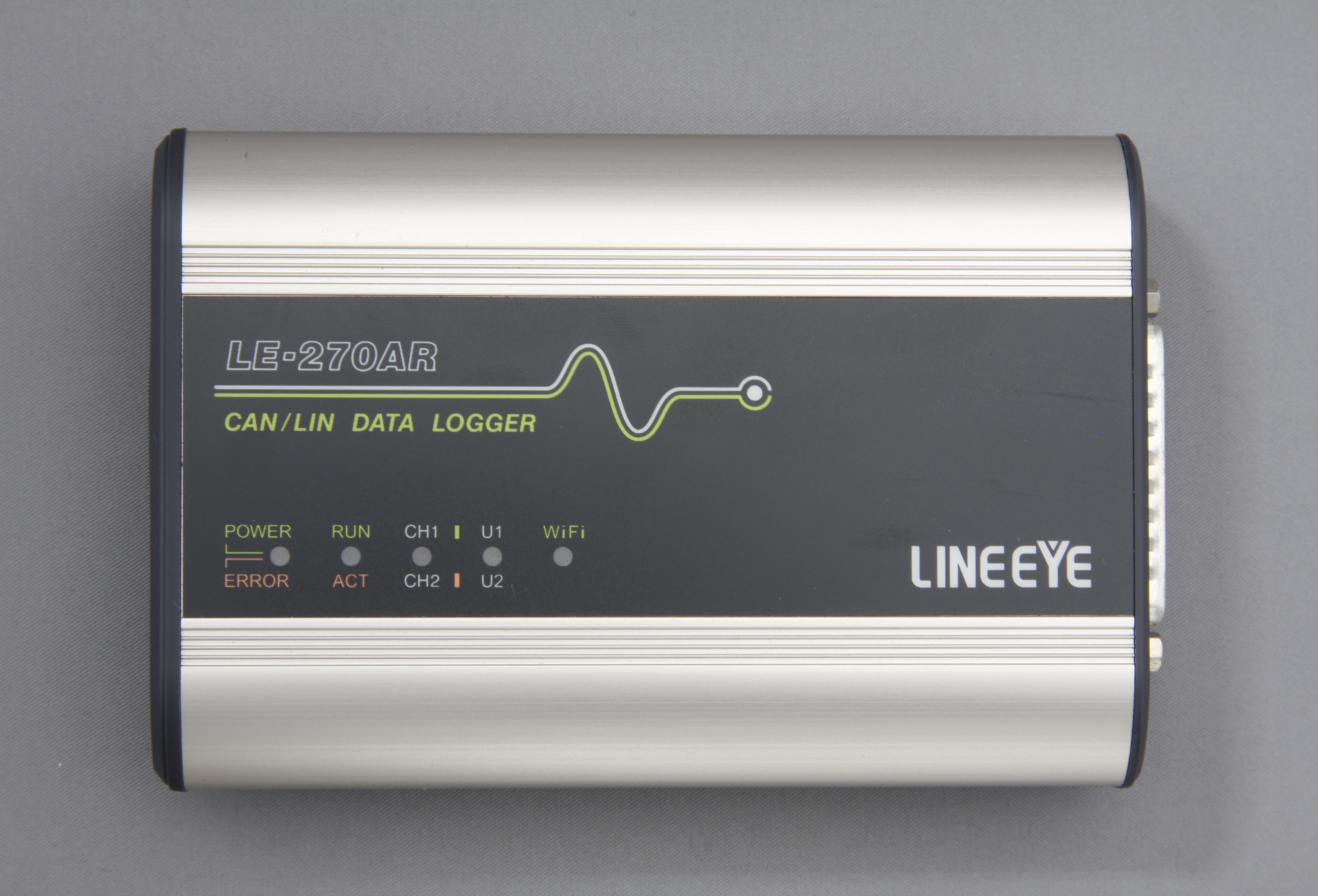
| LED | 5 two-color LED: Power/Error, Test/Record, CH1/CH2, User-defined U1/U2, and Wi-Fi/GPS | |
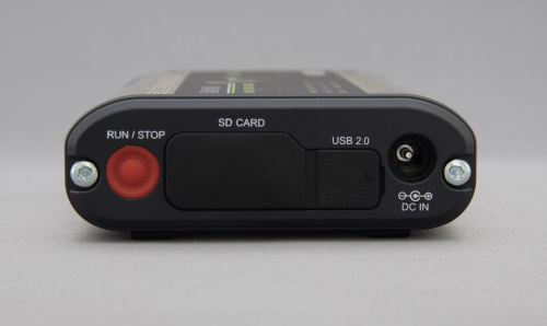
| Switch | One: RUN / STOP | |
| External Trigger Signal | 1 Input, 2 Output (equipped in the measurement connector) | |
| SD/SDHC Card | 2 – 32G byte*2*2 | |
| USB2.0 Port | Mini-B connector. High speed supported. | |
| Wi-Fi | 802.11b/g/n*3 Frequency range: 2400MHz-2483.5MHz Transmission power: +20dBm(802.11b), +17dBm(802.11g), +14dBm(802.11n) |
|
| Power*4 | Powered from USB bus power, DC-IN, or 1pin BATTERY terminal |
|
| Run time during power failure | Approx. 0.5sec | |
| Ambient Temperature, Humidity | In operation: -20 to +60°C, In storage: -20 to +60°C, 20 to 85%RH (No condensation) | |
| Standard | CE (Class A) | |
| Dimension, mass | 86(W)×130(D)×30(H) mm approx. 240g | |
| Environment of PC | OS:Windows® 7/8.1/10 PC: PC/AT compatible | |
| Accessories | PC software, Mini-USB cable, CAN/LIN Dsub cable, Power plug cable, 8G byte SDHC card*2 | |
*1:Only “Hr:Min:Sec”, “Min:Sec:x1ms”is available on Analog mode.
*2:Only SDHC card sold by LINEEYE is supported.
*3:Wi-Fi function is available only in Japan, USA, Canada, and EU nations where the product is needed to be compliant with RE directive (2014/53/EU). The Wi-Fi function of this product is set to invalid depending on the country where it is shipped. Please contact LINEEYE for the detail.
*4:AC adapter is sold separately. In the Remote mode (with PC), the analyzer runs by the USB bus power. In the Logger mode (PC-less), you need to have the optional AC adapter (6A-181WP09) or use the proper external power.
*5:Power supply from connector 1pin consumes abou 30mA even when the power is turned off. If you want to save the power consumption use OBD2-DB25C-1 cable etc.


