PRODUCT
Multi Protocol Analyzer
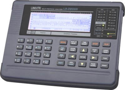
LE-3500R
●Supports UART, I2C, and SPI without option
●Multi-protocol supported
●Mega speed measurement
●Long time recording by AUTO SAVE function
●Logic analyzer analysis and signal voltage measurement
●Supports PC connection and remote control by Wi-Fi
LE-3500R: Japanese model (with Japanese manual)
LE-3500R-E: Abroad model (with English manual)
Specification
| Interface | RS-232C (V. 24) |
|---|---|
| RS-422/485 (RS-530)*1 | |
| TTL(1.8V/2.5V/3.3V/5V level) | |
| Expansion measurement interface*2 | X. 20/21 [OP-SB10N + LE-25Y15] |
| RS-449 [OP-SB10N + LE-25Y37] | |
| RS-530[OP-SB10N] | |
| V. 35 [OP-SB10N + LE-25M34] | |
| TTL (USART) [OP-SB5GL] | |
| Current loop [OP-SB1C] | |
| CAN/LIN [OP-SB7GX] | |
| Expansion firmware*2 | High-speed CC-Link/HDLC/SPI[OP-FW10R] |
| Standard Protocol | ASYNC (Asynchronous), ASYNC-PPP |
| Character synchronous SYNC/BSC | |
| Bit synchronous HDLC/SDLC/X. 25 | |
| I2C, SPI | |
| Modbus | |
| BURST*3 | |
| Optional Protocol | CAN, Devicenet, LIN |
| Synchronous clock | ST1 (DTE transmission clock), ST2 (DCE transmission clock), RT (DCE reception clock), AR (The synchronous clock extracted from the edge of the transmission and reception data) |
| Capture memory*4 | DDR2-SDRAM 64MB SRAM for automatic saving 512KB |
| Baud rate | Full duplex: 2.048Mbps*5/ Half duplex: 2.048Mbps |
| Speed setting range | 50bps to 2.048Mbps Freely set to four effective digits, separately for transmission and reception.(Margin of error: ±0.01% or less) |
| Data format | NRZ, NRZI, FM0, FM1 |
| Data code | ASCII, EBCDIC, JIS7, JIS8, Baudot, Transcode, IPARS, EBCD, EBCDIK, HEX |
| Character framing | ASYNC : Data bit (5,6,7,8) + parity bit (0,1) + stop bit (1,2) |
| Character synchronous : Data bit + parity bit (6 or 8 bits in total) | |
| Bit synchronous : Data bit (8 bits) | |
| Parity bit | NONE, ODD, EVEN, MARK, SPACE |
| Multi-processor bit | MP (multiprocessor) bit is shown with a special mark. |
| Bit transmission order | LSB first or MSB first (switchable) |
| Polarity inversion | Normal or Inverted (switchable) |
| Error check | For all protocols : Parity (ODD, EVEN, MARK, SPACE), Framing, Break, BCC (LRC, CRC-6, CRC-12, CRC-16, CRC-32, CRC-ITU-T). BCC permeation mode. |
| For bit-oriented synchronous protocol : Abort, short frame | |
| Online monitor function | Communication log is recorded continuously and displayed in the LCD without affecting the communication lines. |
| Idle time display | OFF (no record); Resolusion: 100ms, 10ms, 1ms; Max 999. 9 sec |
| Time stamp display | The date and time when the communication data frame was sent and received are recorded. The time unit can be specified as OFF, day/hour/minute, hour/minute/second, minute/second/10ms. * When set to EXTEND:ON, the time stamp is extended to year/month/day/hour/minute, month/day/hour/minute/second, day/hour/minute/second/10msec. (Ver1.06 or later) |
| Line status display | Records and displays the wave form of 4 signals (chosen from RS(RTS), CS(CTS), ER(DTR), DR(DSR), CD(DCD), CI(RI), EXIN(outside trigger input) along with the transmission / reception data. |
| Address filter | Records only frames of the specified address. (only when HDLC / SDLC / X.25) |
| Data display and operations | Pause in capture, scroll, paging, jump to the specified screen. |
| Bit shift display | Entire frame can be shifted to the right or left in 1 bit increments. |
| Protocol translation display | SDLC (modulo 8/128), ITU-T X.25 (modulo 8/128), LAPD, PPP, BSC, I2C, Modbus |
| Line status LED | Two color LEDs of SD, RD, RS(RTS), CS(CTS), ER(DTR), DR(DSR), CD(DCD), CI(RI), ST1(TXC1), ST2(TXC2), RT(RXC). |
| RS-232C | Logic ON (red) , logic OFF (green) , no connection NC (light off) |
| Other I/F | Logic ON (red) , logic OFF or no connection NC (light off) |
| Interval timer | 2kinds; Max. count: 999999 (Resolution: 1ms ,10ms ,100ms) |
| General-purpose counter | 2kinds; Max. count: 999999 |
| Data counter | For SD and RD (1 each): Max. count: 4294967295 |
| Trigger function | Up to four pairs of trigger conditions and actions can be specified. Sequential actions, which validate another condition after one condition is satisfied, are possible. |
| condition | Communication error (Parity, MP, framing, BCC, break, abort, short frame can be specified individually.), communication data string up to 8 characters (don't care and bit mask available), idle time more than the specified duration, match time/counter value, logic status of interface signal line and extarnal trigger input |
| action | Stops measurement/test (number of offsets until a stop can be set), validates trigger conditions, controls timer (start/stop/restart), controls counter (count/clear), activates buzzer, saves monitor data on a memory card, sends the specified character string (during manual simulation), and sends pulse output to external trigger terminal OT2. |
| External trigger output | Sends pulse output to external trigger terminal OT1 when all conditions are satisfied. Sends pulse output to external trigger terminal OT2 according to the trigger output specification. |
| Data search function | Retrieves the data with specific condition from capture memory. |
| condition | Communication error (parity, MP, framing, BCC, break, abort, short frame can be specified individually), communication data string up to 8 characters (don't care and bit mask available), idle time more than the specified duration, specified time stamp, and trigger matching data |
| action | Shows the match data at the top or enumeration display (selectable) |
| Monitor conditions auto setting | Measurement conditions such as protocol, transmission speed, (max. 115.2Kbps), data code, synchronous character and BCC check can be set.*6 |
| Auto run/stop function | Enables measurement to start and end at the specified time at the selected repeating cycle (monthly, daily, hourly). |
| Power ON auto run function | Enables measurement to start automatically after power is turned ON. |
| Auto save function | Automatically saves the monitored data in the capture memory and saves as communications log file in a SD card or USB flash memory. Ring save operation is available by selecting APPEND off (re-recording mode) or APPEND on (append mode). |
| File size | BUF (capture memory size) , 1MB , 2MB , 4MB , 8MB , 16MB, 32MB |
| MAX. files | 1024 |
| Delay time function | Measures and displays the interval of change in the interface signal line. (current/min/max/average, resolution: 0. 1ms) |
| Signal voltage measuring function | Measures and displays the value of voltage amplitude: |
| Statistical analysis function | Takes statistics and displays graphs of transmission/reception data count, number of frames, and satisfied trigger condition count. |
| Logic analyzer function | Measures the logical change of the interface signal in the sampling clock period, and displays its wave. |
| Sampling clock | 1KHz to 20MHz (14 steps) |
| Sampling memory | Min 2,000 |
| Trigger condition | Trigger conditions in the ONLINE monitor functions match. Logical status match between interface signal line and external signal. |
| Trigger position | Before, center, after |
| Zoom in/out | ×8, ×4, ×2, ×1, ×1/2, ×1/4, ×1/8, ×1/16, ×1/32, ×1/64 |
| Other functions | Time measurement by cursor, signal line exchange, signal status search |
| Bit error rate test | Conforming to ITU-T G.821 it measures line quality such bit error rate and block error rate*7. |
| Communication mode | Synchronous (SYNC), Asynchronous (ASYNC) Able to have RTS/CTS flow control |
| Measuring speed | 50bps~2. 048Mbps, freely set to four effective digits |
| Measurement mode | Continuous measurememt, specifies the number of receiving bit, specifies the time to measure, repeatedly measurement at the unit of 1 - 1440 |
| Test pattern | 26-1, 29-1, 211-1, MARK, SPACE, ALT, DBL-ALT, 3in24, 1in16, 1in8, 1in4 |
| Error bit insertion | Inserts 1-bit or 5-bit error in test pattern by key operation. |
| Measurement range | It is able to measure the parameter of the ITU-T advice G.821. Effective received bit (0-65374;9999999), bit errors (0 to 9999999 to 9. 99E9), bit error rate(0 to 9. 99E-9 to 1), block errors (0 to 9999999 to 9. 99E9), block error rate (0 to 9. 99E-9 to 1), Savail(available measurement time: 0 to 9999999sec), loss count (synch loss: 0 to 9999), error duration (0 to 9999999sec), %EFS (normal operation rate: 0. 000 to 100. 000%) |
| Simulation function | Enables transmission/reception test of any given data in DTE or DCE mode (selectable with pin assingnment). |
| Transmit data entry | Transmit data entry: Register 160 kinds of transmission data tables (10Groupsx16, total 16K data) |
| Error data entry | A part of transmission data can be registerd as error data such as parity error. |
| Line control mode | Auto (Controls transmission timing with RS(RTS), CS(CTS), ER(DTR), CD(DCD) signal lines automatically in 1 ms increments) or manual (key operation) can be selected. |
| Transmit driver control | Auto control (turning ON driver only during data transmission) or manual mode (linking with ER (DTR) or CD (DCD) key manipulation) can be selected during RS-485 simulation. |
| MANUAL mode | Sends the data assigned to operation keys each time a key is pressed, while checking communications status on the display. Can be used together with the trigger function |
| FLOW mode | Simulates the X-on /X-off control data and flow control procedures of RTS/CTS control line. (Sender and receiver selectable).*8 |
| ECHO mode | Returns reception data in frames (buffer echo), in bytes (character echo), or by looping back (loopback echo). |
| POLLING mode | Simulates polling communications procedures. (Sender and receiver selectable) |
| BUFFER mode | Reproduces transmission of selected data (SD or RD) captured in memory by monitor function. |
| PROGRAM mode | Creates a simulation program (Max. type: 4, Max steps: 512) using the dedicated commands (38 types) to test the communication procedure. |
| File management function | Measurement data and condition can be saved in a SD card or USB flash. And the format of the data/condition can be used in the PC. |
| File types | Measurement data (.DT), all measurement conditions (.SU), trigger save data (TG SAVEnn.DT), and auto save data (#nnnnnnn.DT) |
| File controls | Normal file display, file display by specified type/created date basis, save, load, delete, delete all, and format |
| Supported memory card | Supported external memory: 2G-32G byte SD card (LINEEYE warrants only the optional SD card.) or a USB flash memory up to 32Gbyte |
| Printout function | Specified range of measurement data can be continuously printed in format corresponding to the display mode. Displayed images can be printed to make hard copies. |
| LCD | Monochrome 240 x 64 dots with backlight |
| Remote Control | PC link software (light edition) is attached*9 The Library to control the analyzer is available. |
| AUX(RS-232C) port | Mini DIN8 pin connector. Communication speed: 9600bps to 230.4Kbps (6 steps) Print out data, Can be used with PC [LE-PC300R], Can be used to upgrade the firmware. |
| SD card slot | Standard size for SD/SDHC memory card. Compatible with the standard of SD association. |
| USB2.0 device port | B-connector in device side. Transfer data in full-speed Can be used with PC [LE-PC300R], Can be used to upgrade the firmware. |
| USB2.0 host port | A-connector in host side. Transfer data in full-speed Can be used to connect with USB flash memory. |
| Wi-Fi Connection | 802.11 b/g/n*10 Frequency range: 2400MHz-2483.5MHz Transmission power: +20dBm(802.11b), +17dBm(802.11g), +14dBm(802.11n) Used for PC connection by LE-PC300R |
| External power supply | Nickel metal-hydride battery (Model: P-19S) |
| Battery operating time*11 | About 7 hours |
| Battery charging time | About 2.5 hours |
| Temperature range | In operation : 0 to 40 degree Celsius, In storage : -10 to 50 degree Celsius |
| Humidity range | 85% (RH) max. |
| Standard | CE(Class A) |
| Dimension, mass | 210 ( W ) x 154 ( D ) x 38 ( H ) mm, About 760g |
| Accessories | Monitor cable for DSUB 25-pin (LE-25M1), Monitor cable for DSUB 9-pin (LE-009M2)*12, DSUB25pin-9pin conversion adapter*12, 5 wires TTL prove cable (LE-5LS), AC adapter (6A-181WP09), carrying bag (LEB-01), Utility CD, instruction manual and warranty |
*1: To monitor control line, expansion board “OP-SB10N” (which has RS-530 port) is needed.
*2: To use the function, the optional accessories described in the brackets are required.
*3: This mode is used to capture all data in synchronization with clock edges.
*4: Transmission/reception data, idle time, time stamp, and line status items consume 4 bytes of memory at each capture.
*5: 1 Mbps for I2C
*6: This function supports only ASYNC, SYNC/BSC, HDLC/SDLC. Correct auto settings are impossible if the amount of communications data is small or communications data includes a large number of errors.
*7: Only ASYNC mode and SYNC mode are available.
*8: Only ASYNC is available.
*9: This is the light edition of optional product “LE-PC300R” (with some limitation for its functions).
*10: Wi-Fi function is available only in Japan, USA, Canada, and EU nations where the product is needed to be compliant with RE directive (2014/53/EU). The Wi-Fi function of this product is set to invalid depending on the country where it is shipped. Please contact LINEEYE for the detail.
*11: The battery operating time was measured under LINEEYE's measurement conditions with the LCD backlight turned OFF.
*12: The options have been substituted by LE-009M2 and DSUB25pin-9pin conversion adapter from LE-009M1 and LE-259AD after the production of Oct. 2019.