PRODUCT
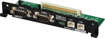
CAN FD/CAN/LIN Expansion Kit
OP-SB7XL
Specification
| Applicable Analyzer | LE-3500XR(V2)/LE-2500XR(V2)/LE-3500XR/LE-2500XR |
|---|---|
| Interface | CAN FD/CAN: Conforms to ISO11898-1:2015/ISO11898 (Dsub 9-pin male connector x2, inch screw #4-40) LIN: Conforms to ISO9141 (Header 3-pin connector x2) |
| Transceiver | CAN/CAN FD: Equivalent to MCP2542FD (Microchip) LIN: Equivalent to TJA1021T (NXP) |
| No. of measurement channels | 2 channels in total with CAN, CAN FD, or LIN in combination |
| Protocol | CAN-FD(ISO/Non-ISO), CAN2.0B, DeviceNet, LIN |
| Capture memory | 100M bytes, 2 divided use is available. By the Auto Save function it can records data up to 32GB to an external storage. |
| Speed | CAN: 20kbps to 1Mbps CAN FD: 20kbps to 1Mbps. 1Mbps to 5Mbps for the data field when BRS is on. LIN: 400bps to 26kbps (Arbitrary speed can be set with 4 significant figures.) |
| Monitor function | Displays and records communication frame ID, type, content, error, and CRC CAN/CAN FD sampling point (60%-90%) setting is available. |
| ID fileter function | Filters (bit mask can be specified) that record only the specified ID for each channel can be set. |
| Error check function | CAN/CAN FD: ACK error, form error, CRC error, error frame LIN: Checksum error, framing error, break field error, sync field error, response error, length error, parity error |
| Time stamp function | Records and displays frame reception time (switchable between real time and difference time from previous frame) Time resolution: Hour/minute/second, minute/second/1ms, 100µs, 10µs, 1µs (100µs, 10µs, 1µs is elapsed measurement time, max 134,217,727) |
Simulation function | Registered communication frames can be sent by key operation or continuously at specified intervals. Up to 16 types of CAN / CAN FD frames can be registered and sent simultaneously in individual cycles. Up to 16 LIN IDs and responses can be registered and used for schedule transmission (master mode) and ID match response (master mode/slave mode) |
| Trigger function | The measurement operation can be controled by specifying up to 4 sets of trigger conditions and operations |
| Trigger condition | Error, specified ID and data (up to 8 characters, don't care and bit mask can be specified, offset from frame start to judgment data can be specified), timer/counter value match, logical state of external signal/external trigger input |
| Trigger action | Buzzer, measurement stop, save measurement data to SD card/USB flash memory, timer control, counter control, enable/disable trigger condition, transmit specified CAN/CAN FD frame, output pulse to TRGOT terminal |
| External trigger | TTL level input, transistor output 5V pull-up 10KΩ |
| External signal input | 4 inputs - Records and displays signal voltage and digital value at the time of data reception and at specified cycle. Real-time display with line state LEDs (DR, CD, CI, ST1) is available. Measurement range of signal voltage value: ±18V. Digital threshold: ON - about 2V or more, OFF - about 1V or less |
| Search function | Search and count of error, frame of specified ID and data (up to 8 characters, don't care and bit mask can be specified, offset from frame start to judgment data can be specified), real-time time stamp of specified range, trigger match data, and external signal logic are avaialble. Mark jump to frame pointer is available. |
| Other functions | Auto Save function, Auto Backup function, Auto Run function, timing waveform display (logic analyzer) function, J1939 parameter display function, file management function |
| Composition | Dedicated expansion board, DB9 monitor cable x 2, 3-wire probe cable x 2, 8-wire probe cable, manual, warranty |