PRODUCT
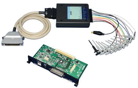
TTL/I2C/SPI Expansion Kit
(For LE-8200A/8200)
(For LE-8200A/8200)
OP-SB85L


Specification
| Applicable Analyzer | LE-8200A/LE-8200 | ||||||||
|---|---|---|---|---|---|---|---|---|---|
| Interface | TTL / CMOS (for I2C and SPI) | ||||||||
| Probe Signal | SD (SDA/SDO) , RD (SDI) , RS (SS) , CS , EX IN , SD CLK (SCL/SCK) , RD CLK , Trigger IN , Trigger OUT (Length of lead:170mm) |
||||||||
| Protocol | ASYNC, ASYNC-PPP, SYNC(BSC), HDLC(SDLC), BURST, I2C, SPI | ||||||||
| Test function | Monitor / Simulation / BERT*1 | ||||||||
| Communication speed | ASYN, ASYNC-PPP, SYNC, BURST: 50bps ~ 4Mbps*2 HDLC: 50bps to 4Mbps*2 on standard, 115.2Kbps to 12Mbps*3 on using OP-FW12G/OP-FW12GA SPI: 50bps to 2.15Mbps*4, 115.2Kbps to 20Mbps*5 on using OP-FW12G/OP-FW12GA I2C: max. 1Mbps (On simulation 50K, 100K, 200K, 384K, 417K, 1Mbps) |
||||||||
| Signal level | Selectable from 5.0V/3.3V/2.5V/1.8V of power supply system | ||||||||
| Input Impedance | 100KΩ( 0V ≤ Vin ≤ 5V) (Acceptable Input range: -1V to +7V) | ||||||||
| Input Level Threshold | Setting of 5.0V High: Min 3.5V Low: Max 1.5V Setting of 3.3V High: Min 2.0V Low: Max 0.8V Setting of 2.5V High: Min 1.7V Low: Max 0.7V Setting of 1.8V High: Min 1.2V Low: Max 0.6V |
||||||||
| Output circuit | The followings are selectable*6: OC(Open collector)with the pull-up resistor of 680Ω, OC(Open collector)without pull-up resistor, Push-pull output of CMOS |
||||||||
| Output Level Voltage | High level: Min Selectable signal level - 0.4V Low level:Max 0.5V*7 | ||||||||
| Analog Waveform | Measure signal voltage of 2 channels and display in analog waveform
|
||||||||
| Digital Waveform | Sampling: 1ms - 10ns sampling, 16 steps | ||||||||
| Size and Weight | Probe Pod body size: 78(W) × 92(D) × 22(H) mm, Relay cable length: 800mm Weight: about 100g |
||||||||
| Power | Supplied from the analyzer's body | ||||||||
| Temperature | Operation: 0 to 40°C Storage:-10 to 50°C | ||||||||
| Accessories | Dedicated expansion board, relay cable, high-speed TTL probe pod, 3-wire probe cable, probe unit |
*1: In BURST(Mode for sampling data at all clock edges), only the monitor mode is supported. I2C and SPI do not have the BERT function.
*2: Applied in the half duplex. In the full duplex 2.15Mbps at Max.
*3: Applied in the half duplex. In the full duplex 6Mbps at Max.
*4: MAX 20Mbps(Monitor) or 4Mbps(Simulation), when the continuous transfer speed is within 1K bytes.
*5: Applied in the monitor mode. In the simulation mode, the speed is up to 12Mbps.
*6: Set from the analyzer. CMOS outputting is recommended on simulation of which speed is more than 2Mbps.
*7: Applied when the current is 4 mA.