Dsub9pin connector
| Pin Number | Singnal Name | Meaning |
|---|---|---|
| 1 | - | |
| 2 | CAN_Low | Bus signal of CAN (low) |
| 3 | SG | Signal ground |
| 4 | - | |
| 5 | FG | Frame ground |
| 6 | - | |
| 7 | CAN_High | Bus signal of CAN (high) |
| 8 | - | |
| 9 | IN | General-purpose input* |
*: When this pin is used as the external power pin, the power supply condition of analyzer can be checked through it`s line state LEDs.
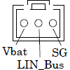
Header 3 pin connector
When using 3-line probe cable (attached accessory)

| Probe Cable | Singnal Name | Meaning |
|---|---|---|
| Lead wire of red | Vbat | DC9-18V input |
| Lead wire of blue |
LIN_Bus | Bus signal of LIN |
| Lead wire of black | SG | Signal ground |
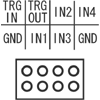
Header 8 pin connector
When using 8-line probe cable (attached accessory)

| External I/O cable | Singnal Name | Meaning |
|---|---|---|
| Lead wire of black |
GND | Signal ground |
| Lead wire of brown | TRG IN | External trigger input |
| Lead wire of red | TRG OUT | External trigger output |
| Lead wire of orange | IN1 | General-purpose input1 |
| Lead wire of orange | IN2 | General-purpose input2 |
| Lead wire of orange | IN3 | General-purpose input3 |
| Lead wire of orange | IN4 | General-purpose input4 |
| Lead wire of black | GND | Signal ground |