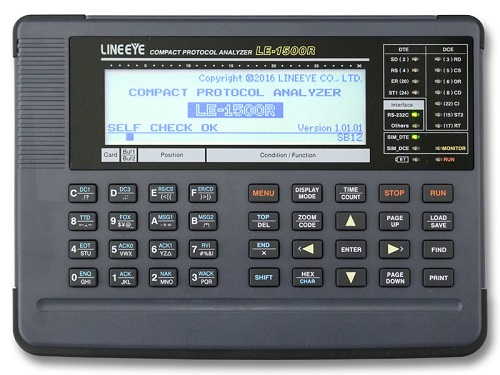
LE-1500R
●Supports capturing of max.500Kbps (full duplex)
●32MB capture memory
●Support data recording up to 16GB by SD card / USB flash
●Light weight(760g), A5 size, 7 hours continous work by battery
LE-1500R: Japanese model (with Japanese manual)
LE-1500R-E: Abroad model (with English manual)
The LE-1500R is a perfect model of a stand-alone communication protocol analyzer which has a touch panel color display and adopted lithium ion battery while inheriting all the functions of the conventional model LE-3500/LE-3500R which have the monitor function, simulation function, and bit error rate test function necessary for communication analysis test.
Visualization of signal status and error data on the line monitor display is dramatically improved by colorizing the display. With the touch panel and the physical key switch, you can optimize the use of them - for example, swiping of the touch screen for display of a large amount of communication monitor data and key operation for MANUAL simulation mode (in which communication test data are assigned to the keys and transmission/reception test is executed). In addition, many key operations of the conventional model are inherited as shortcut key operations.
The newly designed housing that can built in a lithium-ion battery pack (which can be charged from the micro USB connector) is significantly smaller and lighter than the conventional model, reducing the burden for maintenance of communication device and trouble shooting of communication systems.
LE-1500R serves for evaluation of RS-232C serial communication, RS-422/RS-485 lines for railway, aviation, and manufacturing lines where reliability is important, and Modbus communication systems. It also serves for a development of embedded firmware of I2C and SPI devices and communication tests of in-vehicle network devices.
This model is discontinued. The successor (upper model) is LE-2500XR.


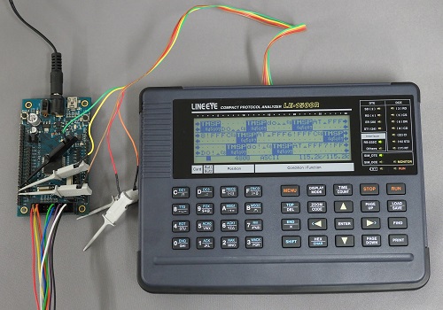
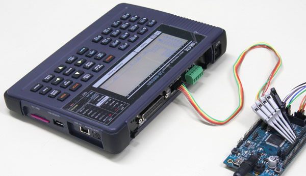
Supports TTL without option
The analzyer has a TTL (1.8V to 5V) measurement port as standard equipment. Without using an optional board the analyzer can do monitoring and test of modules of UART interfaces such as AD conversion ICs and memory ICs.
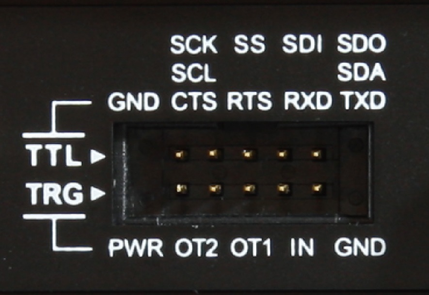
2.54mm pich pin header connector
Equivalent to HIF3FC-10PA-2.54DS(71) HIROSE ELECTRIC
TTL line: UART, I2C, and SPI measurement terminals
TRG line: External trigger I/O and PWR terminal
* PWR terminal outputs the selected signal level voltage (1.8/2.5/3.3/5V).
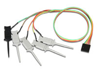
It can be used for connection of TTL communication signals and external trigger signals.
If you use both at the same time, please purchase extra.

Measure at Arbitrary Speed
Able to have a measurement test of high-speed communications up to 500Kbps (half duplex and full duplex). Using high precision DPLL technology for open baud rate support, transmission and reception speeds can be separately set to an effective 4 digits
<Baud rate setting>
Support RS-232C/RS-422/RS-485 and TTL as Standard Feature
■Support RS-232C/RS-422/RS-485 and TTL as Standard Feature
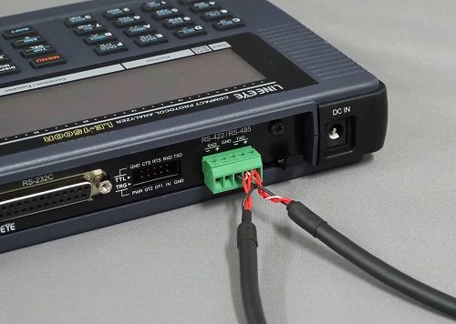
The analyzer has RS-232C, RS-422/RS-485, and TTL as its standard interface. RS-422/RS-485 connector of the analyzer is removable terminal.
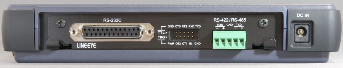


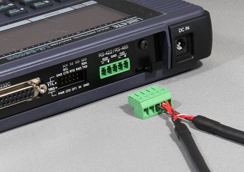
■Detachable terminal block for the RS-422/485 port
The RS-422/485 cable can be directly connected and when you want to take the analyzer awasy from the line you just needs to detach the terminal block.
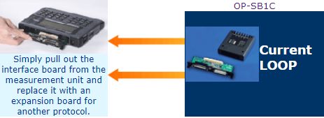
■Expansion kits supports Current loop communciation.
Protocols of differing hardware specification is supported by simply changing the measurement boards.
Long time recording by AUTO SAVE function
The auto save function makes it possible to continuously save up to 16Gbyte. It automatically saves the content of the capture memory into a SD card or USB flash. And it continuously saves data into the measurement log of a user-specified file size, using ring recording as long as the card has space. In addition, it is useful for identifying communication failures which occur at rare intervals.
| Target Line Speed (bps) | Continuous Recording Time Reference*1 | |
|---|---|---|
| Main memory only | When Using 16GB external memory*2 | |
| 9600bps | Approx. 1.8hrs. | Approx. 40days |
| 115.2Kbps | Approx. 9min. | Approx. 80hrs. |
| 500Kbps | Approx. 22min. | Approx. 20hrs. |
| Saving the captured data to USB flash or SD card | External memory up to 16GB |
|---|---|
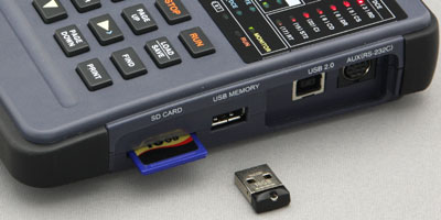 |
Supports optional SD card (such as SD-16GX) or USB flash |
Logic analyzer analysis and signal voltage measurement
Communication line timing is analyzed and displayed as a logic analyzer display to a time resolution of max. 50ns. The new function of signal voltage measurement ensures ease of the voltage measurement of RS-232C signals and voltage swing of TTL in places where tester probes cannot reach smoothly.
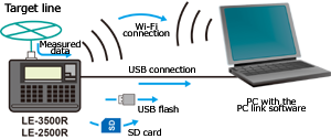
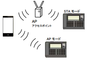
Supports PC connection and remote control by Wi-Fi
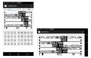
Measurement data can be used on your PC with the light edition of the PC link software attached to the analyzer, or by using free text conversion software or print data acquisition software. The PC link software supports USB connection and Wi-Fi connection (Wi-Fi function is supported only in Japan, USA, Canada, and EU), and remote measurement is possible by connecting multiple analyzers at the same time. It also supports display of measurement data saved in a memory card or USB memory, data conversion, etc. In addition, by using the Android application "LE-REMOTE4" with a smartphone or tablet, you can also remotely control the analyzer from a smartphone with a Wi-Fi connection.
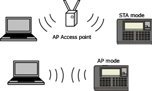
The Wi-Fi connection can be used via an access point or direct connection.
Online monitoring
The online monitor function, like a sniffer, records telegrams in the capture memory and provides an easy-to-understand display for the type of protocol, without affecting the communications line.
LINE EYE protocol analyzers record not only communications data but the time (time stamp) of transmissions and receptions as well as idle time. Therefore, failure time and timeout status can be checked.
As a standard feature, the analyzer support various communications standards from asynchronous to packet switching systems.
Depending on the test, you can select bit transfer sequence and polarity, as well as modulation format from NRZ, NRZI, FMO and FM1. The feature allows to support effective analysis by omitting SYN codes and using SDLC/HDLC address filter.
■Special data items are expressed in individual signs.
Display special data items such as errors in individual signs.
 |
Block check code (Normal) |
 |
Block check code (Abnormal) |
 |
Parity error |
 |
Framing error |
 |
Parity and Framing Error |
 |
Break |
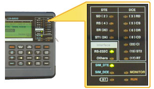
■Line State LED
Communications line state is indicated in real time using 2-color LEDs.
■Time Stamp measurement
Record the data and the time of transmission / reception for data frames. ASYNC cannot recognize the length of frame. Thus, our analyzers decide the frame end when it finds the specific character, or when it passes the specific time of being non-communication. Time stamp will be displayed in above 2 situations.
■Idle Time measurement
The amount of idle time between communications frames can be measured.
■Trigger function
The trigger feature allows you to specify a communications event as the trigger condition and have measurement operations executed automatically when that condition is specified. Up to four pairs of conditions and operations can be set, which is helpful towards identifying frequent intermittent faults that occurs with communications systems. And, the operation of a trigger condition can be specified as the condition for another trigger, making it possible to analyze complicated operations based on sequential trigger.
| Trigger Condition | Communication error (Parity, MP, framing, BCC, break, abort, short frame can be specified individually.), communication data string up to 8 characters (don't care and bit mask available), idle time more than the specified duration, match time/counter value, logic status of interface signal line and external trigger input |
|---|---|
| Trigger Action | Stops measurement/test (offset can be set), validates trigger condition controls timer (start/stop/restart), controls counter (count/clear), activates buzzer, saves monitor data on a memory card, sends the specified character string (during manual simulation), and sends pulse to external trigger terminal OT2. |


Monitor Condition Auto Setting
The analyzers can analyze communications data and automatically set basic measuring conditions, such as communications speed, character framing, data code, synchronization character, BCC/FCS, etc. This is effective for monitoring lines of unknown communications conditions.

Delay Time Measurement
A feature to measure the voltage of four RS-232C signal lines has been added to the conventional delay time function used to analyze the delay time of control line changes (e.g., RTS to CTS changes) at a resolution of 0.1ms.
<Delay time measurement>
Simulations
With the simulation feature, the LINE EYE protocol analyzers act as the counterpart to the target device and perform transmission and reception tests according to protocol. Even in the early stages of development when matching devices are not available, tests can be run at near to actual operating status. After checking the communications protocol step by step in the analyzer's own original MANUAL mode, a developer can create a simple program to branch conditions using menu selection and test more complicated communications protocols.
Communications speed can be freely set. Therefore, margins can be evaluated by intentionally shifting communications speed, and error response processing can be checked using test data that mixes in data with parity errors.
■ MANUAL Mode
The manual mode allows you to send the data registered in the transmission table which corresponds to the "0" to the "F" keys. The data can be set with one press of a key. By using expansion data table, with 10 table groups of “0” to “9” you can select the send data from max 160 data. While checking replies from a unit under development with the monitoring feature, you can easily and simply test the communications process. You can also send fixed data by registering it under a key combination of the SHIFT and "0" to "D" keys, as well as turn RTS/CTS and DTR/DCD signal lines on/off with the SHIFT and "E"/"F" key combinations.
<Transmission table setup display>
■ FLOW Mode
Flow control can be simulated on the transmission and reception-lines using X-on/off flow control or the control line handshake. In the transmission mode, up to 16 cycles of data from transmission start until a generated interrupt request can be displayed. In the reception mode, you can set the number of received data cycles until a transmission interrupt request is generated, as well as the time until the transmission resume request is generated.
<Flow control test setup display>
■ ECHO Mode
In the echo mode, the analyzer internally return received data. Buffer echo to send back data by a reception frame, character echo to send back data by a character and loop back echo that simply loops back data can be selected. It is used to test display terminals and communications terminals.
<ECHO mode setup display>
BERT(Bit Error Rate Test)
BERT support enables you to measure transmission quality of communications lines by a loop-back or interactive connection. It is possible to measure evaluation parameters (bit error count, block error count) conforming to ITU-T G.821 Notification, hence enabling bit error rate evaluations and fault point identification. Elaborate test patterns and functions such as bit error forced interrupt are comparable to dedicated equipment.
<BERT setting display>
Evaluation is possible in ASYNC or SYNC mode, by specifying measurement period (continuous, received bits, duration) or test pattern.
<BERT measurement display>
Once started, the results of measured line quality are displayed and updated in real time.
[BERT Measurement Content]
| Communication mode | Can select the ASYNC or SYNC mode. | ||||||||||||||||||||||||||||||
|---|---|---|---|---|---|---|---|---|---|---|---|---|---|---|---|---|---|---|---|---|---|---|---|---|---|---|---|---|---|---|---|
| Test Pattern |
|
||||||||||||||||||||||||||||||
| Pattern | 26-1, 29-1, 211-1, MARK, SPACE, ALT, DBL-ALT, 1in4, 1in8, 1in16, 3in24 | ||||||||||||||||||||||||||||||
| Measured Data |
|
Menu-Based simple operation
Anyone can easily operate the analyzer owing to the easy menu selection system handed down from earlier models.
<Top menu display>
Offline Analysis and Data Searches
Measurement data displays can be freely scrolled and paged. A powerful search feature allows you to locate specific data and perform counting.
Search Key
Communications error (individual error type can be specified), communications data string of max. 8 characters (DON'T CARE and bit mask can also be specified), idle time beyond a specified duration, specific time stamp (DON'T CARE can also be specified), external trigger matching data
Search Operation
Find and display, counting
<Search key setting>

Using "DON'T CARE (*)," you can search for time stamp data from 10:30:00 to 10:39:59 as in this example.
Measurement data displays can be freely scrolled and paged. A powerful search feature allows you to locate specific data and perform counting.
| Search Key | Communications error (individual error type can be specified), communications data string of max. 8 characters (DON'T CARE and bit mask can also be specified), idle time beyond a specified duration, specific time stamp (DON'T CARE can also be specified), external trigger matching data |
|---|---|
| Search Operation | Find and display, counting |
<Search key setting>
Using "DON'T CARE (*)," you can search for time stamp data from 10:30:00 to 10:39:59 as in this example.
PC Compatible File Management Specification
Test conditions and results such as measured data can be saved on optional SD cards or USB flash in the file management format compatible with your PC. Of course, files can be interchangeably used between models. Therefore, measurement data can be saved on-site with LE-1500R, and analyzed or manipulated in greater detail using LE-1500R back in the office.
※ The LE-8200(A), LE-3500(R), LE-2500(R), LE-1500, LE-7200, LE-3200, LE-2200, and LE-1200 are compatible in measurement data file. Part of files or data saved in higher hierarchy models or new models, hower, may not be available in lower hierarchy models or conventional models.
<File operation display>
Types, names, sizes and the data/time of files saved in the memory card can be checked.
File type
Measurement data (.DT), Trigger save data (TG SAVEnn.DT), Auto save data (#nnnnnnn.DDT), Measurement Conditions (.SU)
File operation
Displaying normal file or designated type of files, Save, Load, Deletion, Format
<File filter setup>

When many files have been saved, the file filter feature allows you to specify the type of file to be displayed.
This is set to display data betwen 0:00 on August 1, 2008 and 23:59 on August 31, 2008.
Test conditions and results such as measured data can be saved on optional SD cards or USB flash in the file management format compatible with your PC. Of course, files can be interchangeably used between models. Therefore, measurement data can be saved on-site with LE-1500R, and analyzed or manipulated in greater detail using LE-1500R back in the office.
<File operation display>
Types, names, sizes and the data/time of files saved in the memory card can be checked.
| File type | Measurement data (.DT), Trigger save data (TG SAVEnn.DT), Auto save data (#nnnnnnn.DDT), Measurement Conditions (.SU) |
|---|---|
| File operation | Displaying normal file or designated type of files, Save, Load, Deletion, Format |
<File filter setup>
When many files have been saved, the file filter feature allows you to specify the type of file to be displayed.
This is set to display data betwen 0:00 on August 1, 2008 and 23:59 on August 31, 2008.
Updating to Firmware
You can download the latest version of software from our website to take advantage of the latest functions and features.
-> Download
You can download the latest version of software from our website to take advantage of the latest functions and features.
-> Download
Auto RUN/STOP for Unmanned Measurement
By setting time and a data of measurement start and end, measurement can be done automatically during the specified time period.
<Auto run display>
Various Print Formats
Measurement data of a user-specified range can be printed out continuously from any printer. And, with a dedicated printer, you can print hard copy images of computer displays and continuous images of logic analyzer waveforms.
[ Printing Sample image ]
- Normal data
*=[LE-1500R]=====[2015-02-07 15:18:29]=* * Model : LE-1500R * * Version : 1.00 * * Extension : Standard * * Serial No.: XXXXXXXX * * Start time: 2015-02-07 15:17:29 * * Stop time : 2015-02-07 15:17:31 * *-------------------------------------* * MONITOR DATA * * PROTOCOL: ASYNC * * S-SPEED : 9600 R-SPEED : 9600 * * CODE : ASCII CHAR BIT: 8 * * PARITY : NONE STOP BIT: 1 * * BCC : NONE * * IDLE TM : 1ms TM STAMP: MS10m * * PRINT CODE : ASCII * *=====================================* SD:[ IDLE ][ TMSP ]52435252430D[ TMSP ] - - - - - -[ IDLE ] [ 0664 ][322868] R C R R CCR[322869] [ 0051 ] RD: - - - - - - 0D0A4F4B0D0A CRLF O KCRLF SD:[ TMSP ]52435252430D[ TMSP ] - - - - - -[ IDLE ][ TMSP ] [322920] R C R R CCR[322921] [ 0071 ][322993] RD: - - - - - - 0D0A4F4B0D0A CRLF O KCRLF SD:52435252430D[ TMSP ] - - - - - -[ IDLE ][ TMSP ]52435355 R C R R CCR[322994] [ 0063 ][323058] R C S U RD: - - - - - - 0D0A4F4B0D0A - - - - CRLF O KCRLF SD:430D[ TMSP ] - - - - - -[ IDLE ][ TMSP ]52435355430D[ TM CCR[323059] [ 0041 ][323100] R C S U CCR[323 RD: - - 0D0A4F4B0D0A - - - - - - CRLF O KCRLF SD:SP ] - - - - - -[ IDLE ][ TMSP ]52434155430D[ TMSP ] - - 101] [ 0046 ][323148] R C A U CCR[323149] RD: 0D0A4F4B0D0A - - - - - - 0D0A CRLF O KCRLF CRLF SD: - - - -[ IDLE ] [ 0132 ] RD:4F4B0D0A O KCRLF - Line state
*=[LE-1500R]=====[2015-02-07 15:38:16]=* * Model : LE-1500R * * Version : 1.00 * * Extension : Standard * * Serial No.: XXXXXXXX * * Start time: 2015-02-07 15:37:53 * * Stop time : 2015-02-07 15:38:03 * *-------------------------------------* * MONITOR DATA (WITH LINE STATE) * * PROTOCOL: ASYNC * * S-SPEED : 9600 R-SPEED : 9600 * * CODE : ASCII CHAR BIT: 8 * * PARITY : NONE STOP BIT: 1 * * BCC : LRC E * * IDLE TM : 1ms TM STAMP: MS10m * * PRINT CODE : ASCII * *=====================================* SD: [ TMSP ]02303132333435363738394142434445464748494A4B [375945]SX 0 1 2 3 4 5 6 7 8 9 A B C D E F G H I J K RD: - - - - - - - - - - - - - - - - - - - - - - RS:01111111111111111111111111111111111111111111111111111111 CS:00011111111111111111111111111111111111111111111111111111 CD:00000000000000000000000000000000000000000000000000000000 ER:11111111111111111111111111111111111111111111111111111111 SD:4C4D4E4F505152535455565758595A0319 [ TMSP ]02 L M N O P Q R S T U V W X Y ZEX{} [380152]SX RD: - - - - - - - - - - - - - - - - - - RS:11111111111111111111111111111111111000000001111111111111 CS:11111111111111111111111111111111111110000000011111111111 CD:00000000000000000000000000000000000000000000000000000000 ER:11111111111111111111111111111111111111100111111111111111 SD:303132333435363738394142434445464748494A4B4C4D4E4F505152 0 1 2 3 4 5 6 7 8 9 A B C D E F G H I J K L M N O P Q R RD: - - - - - - - - - - - - - - - - - - - - - - - - - - - - RS:11111111111111111111111111111111111111111111111111111111 CS:11111111111111111111111111111111111111111111111111111111 CD:00000000000000000000000000000000000000000000000000000000 ER:11111111111111111111111111111111111111111111111111111111 SD:535455565758595A0319 S T U V W X Y ZEX{} RD: - - - - - - - - - - RS:11111111111111111111100000 CS:11111111111111111111111000 CD:00000000000000000000000000 ER:11111111111111111111111110 - PPP translation
*=[LE-1500R]=====[2015-02-07 15:18:29]=*
* Model     : LE-1500R                 *
* Version   : 1.00                    *
* Extension : Standard                *
* Serial No.: XXXXXXXX                *
* Start time: 2015-02-07 15:17:29     *
* Stop time : 2015-02-07 15:17:31     *
*-------------------------------------*
* MONITOR DATA (PPP TRANSLATION)      *
*  PROTOCOL: PPP                      *
*  S-SPEED : 57600   R-SPEED : 57600  *
*  CODE    : HEX     FCS     : FCS16  *
*  IDLE TM : 1ms     TM STAMP: MS10m  *
*=====================================*

-----TM---PROTOCOL-CODE------ID-FC---------------------DATA--------------------
SD:580943 LCP      CONF-REQ   0  G 00320206000000000506289B6DD2070208020D030611
RD:580982 LCP      CONF-REQ   1  G 0020010405F40206000000000305C223050702080213
RD:580984 LCP      CONF-REJ   0  G 000B0D03061104064E
SD:580984 LCP      CONF-ACK   1  G 0020010405F40206000000000305C223050702080213
SD:580985 LCP      CONF-REQ   1  G 002B0206000000000506289B6DD20702080213170143
RD:580998 LCP      CONF-ACK   1  G 002B0206000000000506289B6DD20702080213170143
RD:580999 CHAP     CONF-REQ   1  G 0021107D1A3C2B864ADCE51A19A8B4C44C1E9A6E6173
SD:580999 LCP      IDENT      2  G 0012289B6DD24D5352415356352E3030
SD:581000 LCP      IDENT      3  G 001E289B6DD24D535241532D312D4550534F4E5F4544
SD:581000 CHAP     CONF-ACK   1  G 00341084B08E8379CF63E95DB30B06FE74295C706C75
RD:581033 CHAP     CONF-NAK   1  G 000500
RD:581033 IPCP     CONF-REQ   1  G 00100206002D0F010306D299F828
SD:581033 CCP      CONF-REQ   4  G 000A120600000001
SD:581033 IPCP     CONF-REQ   5  G 00280206002D0F010306000000008106000000008206
SD:581034 IPCP     CONF-ACK   1  G 00100206002D0F010306D299F828
RD:581046 LCP      PROT-REJ   2  G 001080FD0104000A120600000001
RD:581047 IPCP     CONF-REJ   5  G 0010820600000000840600000000
SD:581047 IPCP     CONF-REQ   6  G 001C0206002D0F010306000000008106000000008306
RD:581057 IPCP     CONF-NAK   6  G 00160306D28B420D8106CAEF71128306CAEF711A
SD:581058 IPCP     CONF-REQ   7  G 001C0206002D0F010306D28B420D8106CAEF71128306
RD:581069 IPCP     CONF-ACK   7  G 001C0206002D0F010306D28B420D8106CAEF71128306
SD:581083 IP       (45)       0  G 01480725000080111DE8D28B420DFFFFFFFF00440043
SD:581482 IP       (45)       0  G 01480726000080111DE7D28B420DFFFFFFFF00440043
SD:582369 IP       (45)       0  G 003B072700008011E2F0D28B420DCAEF711204D20035
RD:582385 IP       (45)       0  G 009CF4154000F7113EA0CAEF7112D28B420D003504D2
SD:582389 IP       (45)       0  G 0030072840008006CBCDD28B420DCF2E440B04D30050
RD:582403 IP       (45)       0  G 0030C64C4000370655A9CF2E440BD28B420D005004D3
SD:582404 VJUTCPIP (45)       0  G 0028072A40008000CBD3D28B420DCF2E440B04D30050
SD:582405 VJCTCPIP (70)       0  G 28ED02474554202F20485454502F312E310D0A416363
RD:582430 VJUTCPIP (45)       0  G 0028C79240003700546BCF2E440BD28B420D005004D3
RD:582431 VJCTCPIP (30)      22  G 4004485454502F312E312033303220466F756E640D0A
SD:582437 IP       (45)       0  G 0028072D40008006CBD0D28B420DCF2E440B04D30050
SD:582440 IP       (45)       0  G 0030072E40008006CBC7D28B420DCF2E440B04D40050
RD:582452 VJCTCPIP (2C)      56  G F401000153000130
RD:582452 IP       (45)       0  G 0028C8C7400037065336CF2E440BD28B420D005004D3
SD:582453 VJCTCPIP (6E)       0  G 5B5D00FEAD00015400012204
RD:582454 IP       (45)       0  G 0030C8FB4000370652FACF2E440BD28B420D005004D4
SD:582455 VJUTCPIP (45)       0  G 0028073140008001CBCCD28B420DCF2E440B04D40050
SD:582457 VJCTCPIP (70)       1  G C75B02474554202F686F6D652E61726D782048545450
RD:582478 VJUTCPIP (45)       0  G 0028CA6A400037015193CF2E440BD28B420D005004D4
RD:582481 VJCTCPIP (20)      66  G DA0B485454502F312E3120323030204F4B0D0A536572
RD:582507 VJCTCPIP RES-REP   62  G 7E656C6C70616464696E673D2230223E3C74723E3C74
SD:582522 VJCTCPIP (4C)       1  G 346C0005B400012A
RD:582536 VJCTCPIP (2F)     144  G E90002A26173733D22666F726D223E3C666F726D206E
SD:582552 VJCTCPIP (44)       1  G 2EB80005B4
RD:582561 VJCTCPIP RES-REP  249  G DE697374223E3C6120687265663D2231352E61333637
SD:582572 VJCTCPIP (64)       1  G 2
- BERT
*=[LE-1500R]=====[2015-02-07 16:16:51]=*
* Model     : LE-1500R                 *
* Version   : 1.00                    *
* Extension : Standard                *
* Serial No.: XXXXXXXX                *
* Start time: 2015-02-07 16:16:04     *
* Stop time : 2015-02-07 16:16:36     *
*-------------------------------------*
* BERT RESULTS                        *
*  PROTOCOL: ASYNC                    *
*  S-SPEED : 9600    R-SPEED : 9600   *
*  CHAR BIT: 8       STOP BIT: 1      *
*=====================================*

 DATE-TIME     LOSS   R-BIT   E-BIT  BIT-ER   E-BLK  BLK-ER   E-SEC  %E.F.S
02/07 16:00       0  460776       0 0.00E+0       0 0.00E+0       0 100.000
02/07 16:01       0  460768       5 1.09E-5       1 1.37E-4       1  98.305
02/07 16:02       0  460768       5 1.09E-5       1 1.37E-4       1  98.305
02/07 16:03       0  460800       0 0.00E+0       0 0.00E+0       0 100.000
02/07 16:04       0  460800       0 0.00E+0       0 0.00E+0       0 100.000
02/07 16:05       0  460776       0 0.00E+0       0 0.00E+0       0 100.000
02/07 16:06       0  460776       0 0.00E+0       0 0.00E+0       0 100.000
02/07 16:07       0  460776       0 0.00E+0       0 0.00E+0       0 100.000
02/07 16:08       0  460776       0 0.00E+0       0 0.00E+0       0 100.000
02/07 16:09       0  460776       0 0.00E+0       0 0.00E+0       0 100.000
02/07 16:10       0  460776       0 0.00E+0       0 0.00E+0       0 100.000
02/07 16:11       0  460776       0 0.00E+0       0 0.00E+0       0 100.000
02/07 16:12       0  460776       0 0.00E+0       0 0.00E+0       0 100.000
02/07 16:13       0  460776       0 0.00E+0       0 0.00E+0       0 100.000
02/07 16:14       0  460768       0 0.00E+0       0 0.00E+0       0 100.000
02/07 16:15       0  460768      70 1.52E-4      15 2.05E-3       4  93.220
02/07 16:16       0  240096       0 0.00E+0       0 0.00E+0       0 100.000