OP-SB7FX CAN/LIN Communications Expansion Kit
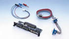
Includes expansion board and firmware for CAN and LIN communications mainly used for in-vehicle network.
Outline
 OP-SB7FX is the expansion kit which makes it possible to monitor, and simulate CAN and LIN communications. It enables monitoring of CAN and LIN data in any combination up to 2 channels at a time. Suitable for evaluation of mixed in-vehicle networks of CAN and LIN.
* LIN (Local Inter Connect Network) is communications protocol for in-vehicle network proposed by automobile manufacturers in Europe.
Operating Instructions
After inserting the expansion board into the analyzer, connect to the CAN BUS using the included monitor cable. For ISO11898, the terminator can be set by use of the jumper pin of the expansion board. You can select CAN (ISO11898 or ISO11519-2) or LIN from your analyzer. For CAN, connect to the CAN BUS using the included CAN monitor cable. For LIN, connect to the LIN BUS using the included LIN monitor cable.<Example of CAN measurement> |
<Example of LIN measurement> |
Monitoring
Since measurement data is recorded with time stamp in 1ms unit at the same time, error timing can be easily detected. Also, efficient analysis is possible by using the ID filter. Supports the standard format (11bit ID) and the expansion format (29bit ID) for CAN. You can customize bit timing for every channel, and measure based on the actual CAN BUS state. You can set speed settings arbitrary and calculation method of the Checksum for every channel in the case of LIN. Sampling Point |
< ID Filter Setup Screen > |
< Bit Timing Customize Screen > |
< LIN Configuration Screen > |
< Data Length and Checksum Setup Screen > |
<Screen of Monitoring CAN/LIN Simultaneously> |
| Display | Meaning |
|---|---|
| TM | Displays the time when the frame is received. (e.g. 4216898 received at 42min 16.898sec.) |
| dT | After finising the measurement, display the elapsed time since receiving the previous frame. Press [ZOOM/CODE] to change to TM screen. (firmware Ver1.02 or later) |
| CH | Displays the channel received. (1: CH1 2: CH2) |
| ID | At the time of CAN, displays the ID of the frame received.At the time of LIN, displays in order of the size of SynchBreak width, SynchField, - and Identifier. |
| TYP | Displays a type of the frame received. DAT: CAN data frame REM: CAN remote frame ERR: CAN error frame FRM: LIN frame ILL: frame that is not applied LIN standard |
| DL | At the time of CAN, displays the contents of data length code (data byte size). (a decimal number) At the time of LIN, displays the data length which is set by CONFIG. (a decimal number) |
| DATA | Displays the contents of the data field. |
| C | Only at the time of LIN, displays the contents of Checksum displayed. (a hexadecimal number) |
| S | Displays whether or not the received frame is normal. |
| I | Displays the status of the external input. |
Trigger
| FACTOR | Contents |
|---|---|
| ERROR | Executed the trigger by an error of LIN. BREAK : Considers as an error when Dominant of BREAK field is 10 bit. SYNC : Considers as an error when the value of SYNC field is other than 55(h). PARITY : Parity Error CHECKSUM : Checksum Error FRAMING : Framing Error (When the stop bit is Dominant.) |
| DATA | Executes the trigger when the specific data frame is received. Sets for the receiving channel, ID, and the contents of the data field. (Settable for DON'T CARE and a bit mask.) |
| REMOTE | Executes the trigger when the specific remote frame of CAN is received. Sets for the receiving channel and ID. (Settable for DON'T CARE and a bit mask.) |
| TM/CT | Executes the trigger when the timer or the counter reaches the value being set. SelectsTM0/TM1 or CT0/CT1. |
| EXTERNAL | Executes the trigger by an external trigger input. Sets RISING or FALLING. |
| ACTION | Contents |
|---|---|
| BUZZER | Sounds for about 0.3 seconds. |
| STOP | Stops the measurement. Sets the time from the occurrence of the trigger to the stop of the measurement as OFFSET. |
| SAVE | Save data of before and after the trigger specified by the OFFSET when the trigger is specified. |
| TIMER | Control the timer. Sets the kind of the timer and the contents of the control. |
| COUNTER | Control the counter. Sets the kind of the counter and the contents of the control. |
| TRIG SW | Controls another trigger state. |
| SEND | Executes the control of the data which is set on the transmission data table. Sets transmission data table, the contents of the control (Transmit or Stop), and the time (RESPONSE) from the occurrence of the trigger to the control. (It is effective only at CAN.) |
Simulation
[CAN]The simulation function makes it possible to transmit the data frame and remote frame of the standard and expansion format with one click. Also, it can transmit changing data at the appointed time in order. Those functions are very useful for development of CAN BUS and DeviceNet equipment.
 |
< CAN Data Table Screen > |
< Data Table Setup Screen > |
< Sweep Data Setup Screen > |
Supports both Master and Slave. At the time of Master, it is possible to perform the data transmission and the one-touch transmission following the schedule.
At the time of Slave, transmits when meeting with ID set to the data table. Also, it is possible to transmit Wake-up (80h) and Error frame (BREAK, SYNC, Parity, Checksum etc.).
< Master Mode Screen > |
< Schedule Setup Screen > |
< Slave Mode Screen > |
< Data Table Setup Screen > |
Specification
| Interface | CAN: Supports ISO 11898/ISO 11519-2 (*1)/DSUB 9-pin connector x 2 LIN: Supports ISO 9141 Header 3-pin connector x 2 |
|---|---|
| Transceiver | CAN: TJA1050/1054 or equivalent LIN: L9637D or equivalent |
| No. of measurement Channel | Max. 2 channels |
| Protocol | CAN, Device Net, LIN (Rev. 1.1, 1.2, 1.3, 2.0) |
| Baud Rate (bps) | CAN: Max. 1 Mbps (*2) LIN: Max. 20 Kbps |
| Function | Monitor / Simulation |
| Time Stamp Measurement | Min. 1m sec |
| Composition | Dedicated expansion board, CAN monitor cable, LIN monitor cable, 3-wire probe cable, firmware CD |