USB protocol analyzer
LE-650H2-A
●Records measurement log up to 40GB on HDD/SSD of PC
●Log search and detailed translation display are available without stopping measurement
●Real-time display of the bus power consumption of the target device
●Statistical information such as the number of bytes transferred and the average transfer rate
●Trigger and filter functions for efficient measurement
●Radiation noise reduction and palm size body by aluminum housing
Product lines: affordable price model, LE-650H2
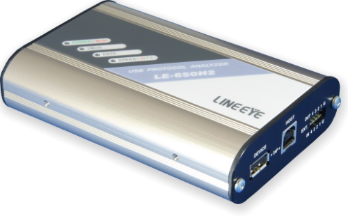
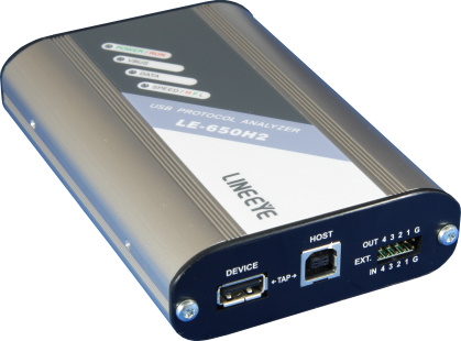
LE-650H2-A is the hardware-based USB analyzer, which can record a large amount of data on the HDD/SSD of the PC, display translation with each class decode, and measure VBUS power consumption. The analyzer automatically detects the High/Full/Low speed of USB2.0/1.1 and starts measuring by simply pressing the space bar of the PC. The low cost device of easy operation by connecting it to the USB port of the PC is useful for developing/debugging the firmware/driver and study purpose of USB standard.
| Standard | USB2.0/1.1 | |
|---|---|---|
| Speed | HIGH (480Mbps)/ FULL (12Mbps)/ LOW (1.5Mbps) Automatically detect and run | |
| Storage Capacity | Analyzer | Capture memory: 128MB |
| PC | HDD/SSD: Max.40GB (Can be specified every 1MB) | |
| Recording Method | Record USB packets, device status*1 (Bus Reset, Suspend, Disconnect, Device Chirp, Hub Chirp, VBUS value) on the HDD/SDD of the PC through the capture memory of LE-650H2 (can record multiple log files continuously). | |
| Time Stamp | Records timestamps along with USB packets and External input trigger log. 16.7ns for 5 hours max., then start from 0 again. |
|
| Packets | SOF, IN, OUT, SEUP, DATA0, DATA1, DATA2, ACK, NAK, STALL, PRE, PING, MDATA, SPLIT, ERR, NYET, Unknown. | |
| Speed Display | Display communication speed per transaction in HS, FS or LS. | |
| Filter | Log | Record (or do not record) SOF, IN-NAK, OUT-NAK, SETUP-NAK, PING with or without multiple particular address/end points. |
| Display | Display (or do not display) SOF, IN-NAK, OUT-NAK, SETUP-NAK, PING with or without multiple particular address/end points. | |
| Trigger | Condition | Particular address/end points, packet type (Token/ Hand shake packets in combination), errors (CRC/ PID), data packets (8byte max, Hex/Decimal/Binary or character input, with or without bit mask.) and bus state (Bus Reset, Suspend, Disconnect), external trigger (edge or level specification possible), VBUS voltage and current. |
| Action | Possible to specify actions enable with log stop, and external trigger output (with or without levels or pulses) in sequence (up to 16 sequence). | |
| External | 4 external trigger input (TTL level) and 4 external trigger output (LVTTL level). Connector: 10pin male (2.54mm pitch 961210-5604 or equivalent) |
|
| Search Function | SOF, IN, OUT, SETUP, PING, ACK, NAK, STALL, NYET, ERR, idle status more than specified value, error (CRC, PID, DATA toggle sequence, transaction structure), MassStorage (SCSI, ATAPI, SFF-8070i), PTP/MTP, Audio, HID, HUB, Printer, Video, Communication, USBTMC class command, unknown log information, specific address/end points in combination, standard request, data search (Hex/Decimal/Binary, character), trigger point, mark. | |
| Color Display Customization | Packets can be color-coded separated. | |
| Detailed Display | Standard requests, peculiar device requests to HUB/HID/Audio/Communication/MassStorage (Bulk Only Transport)/Printer/USBTMC/Video/Wireless controller Class-Specific device request(only for HCI protocol for Bluetooth dongle) class, standard descriptors, each descriptors in HUB/HID/Audio/Printer/USBTMC/Communication/Video class, command of MassStorage/Bulk Only Transport (SCSI transparent command set, supporting SFF-8070i), Operations of MTP/PTP, Responses, events, commands and events of HCI protocol for Bluetooth dongle, class can be displayed in detail. | |
| Statistic analysis function | The total number of transactions, transfer bytes, and the average transfer rate of specified data for each address/end point. | |
| Mark/Jump function | Up to 99 marks can be set (Able to make comments on each mark) | |
| VBUS Measurement Accuracy | Voltage: range 0 to 8V, Accuracy ±1%FS Current: range -0.9A*2 to 1A, Accuracy ±1%FS |
|
| VBus measurement Bar | Display (or do not display) VBus measurement Bar. | |
| VBus logger mode | Measurement Cycle | 0.1ms – 1s (13 steps) |
| Storage Capacity | HDD/SSD: Max.2GB *Automatically stop measurement on getting the data of 400,000,000 sampling(2Gbytes) from the beginning of measurement. |
|
| Graph display | Display voltage, current, and power consumption in graph at real time. | |
| Dump display | Display voltage, current, and power consumption in dump display at real time. | |
| Save | Save log file data, export in text/CSV/binary for data payload, copy/paste via a clipboard. (Able to make comments on saved data.) *VBus logger mode has only the function of saving log files and CSV outputting. |
|
| Print function | Specified ranges of recorded data can be printed. *VBus logger mode does not have this function. |
|
| Measurement port | USB standard A/B receptacle: 1 each | |
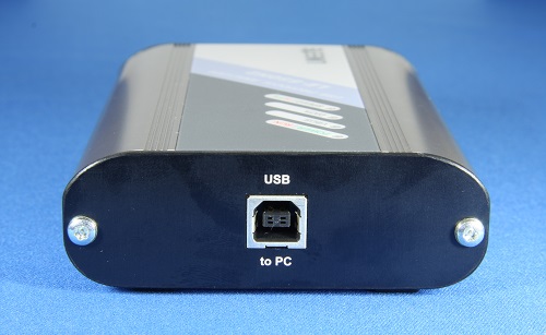
| USB2.0 port | USB standard B receptacle, Connect to the analysis PC | |
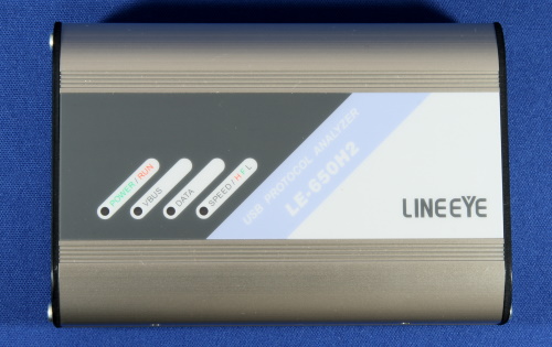
| LED Indicator | 2-colored LED, POWER/RUN, VBUS, DATA, SPEED (High:red, Full:green) | |
| Power Supply | USB Bus power (current consumption: 400mA max) | |
| Ambient Temperature | In operation: 0 to 40°C In storage: -20 to 60°C |
|
| Ambient Humidity | In operation: 20 to 80%RH In storage: 20 to 85%RH (No condensation) |
|
| Standard | CE(class A) | |
| Dimensions, weight | 86(W)×130(D)×30(H)mm, approx.210g | |
| Accessories | Analyzer, PC software CD, USB cable x2 (1.8m/0.9m), Instruction manual, Warranty | |
| System Requirement | Windows® 11/10/8.1/7※3 (Compatible with Japanese and English versions of Windows®) Secondary storage device: HDD or SSD 30MB + free space in communication log recording area |
|
*1: Bus Reset, Suspend, Disconnect are recorded under the following condition.
Note: The USB device status may not coincide with the actual bus state of the applicable device at the time of USB cable connection or disconnection because the D+/D- signals will be unstable.
| Bus Reset | The SEO status of D+/D- signals is detected within a range between 2.5us and 139.8ms. |
|---|---|
| Suspend | A non-communication period not in the SEO status is detected for 3ms or over. |
| Disconnect | The SEO status of D+/D- signals is detected for 139.8ms or over. |
*2: Display a minus value when VBUS current flows from the device to the host.
*3: Not supported when using Windows® 8.1/7.


