(For LE-3500R)
OP-FW10R
OP-FW10R is a firmware to expand the measurement speed for bit synchronous communication such as HDLC/SDLC/X.25, CC-Link and SPI communication up to 10Mbps. Processing major part of the measurement process by FPGA, it enables capturing of communication data with time stamp of micro-second unit.
This is the suitable option for high-speed HDLC such as multi-drop CC-LINK or TTL signal level on a printed-circuit board, or high-speed SPI communication.
Preparation
- Connect the analyzer with a PC by AUX cable or USB cable.
- Set the firmware CD-ROM to the PC.
- Transfer the firmware using the software included in the CD-ROM.
- Once the firmware is installed the analyzer runs in high-speed mode.
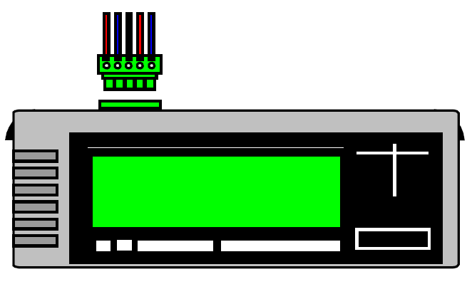
< OP-FW10R opening display >

Following is how to change the normal mode and the high-speed mode.
High-speed mode to normal mode : turn on the power by pushing [Shift] and [0].
Normal mode to high-speed mode : turn on the power by pushing [Shift] and [3].
Operating Instructions
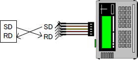
■RS-232C
Connect the RS-232C port of the analyzer with a target line by the monitor cable attached to the analyzer.
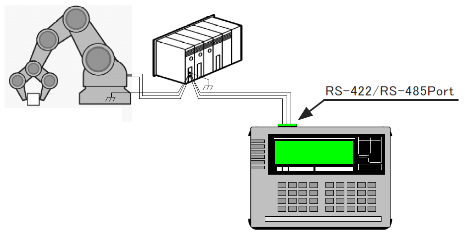
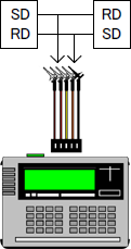
■RS-422/RS-485
Connect the RS-422/RS-485 terminal block of the analyzer with a RS-422/RS-485 target line.
| Half-duplex | TxD +, TxD -, GND |
|---|---|
| Full-duplex | TxD +, TxD -, RxD +, RxD -, GND |
When a terminal resistance is needed, connect the resistance by a jumper pin on the interface board.
■TTL
Connect the TTL port of the analyzer with a target by TTL prove cable attached to the analyzer.
■HDLC Monitor
■HDLC Simulation
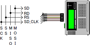
■SPI Monitor
■SPI Simulation
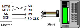
□Master Mode
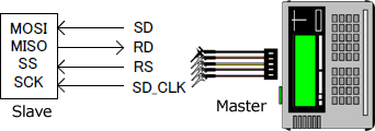
■SPI Simulation
□Slave Mode
Monitor function
■HDLC/SDLC/X.25 and CC-Link
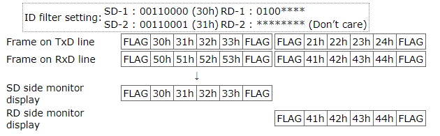
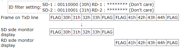
It supports translation display of the frame level or packet level adding to the normal display. You can indicate an ID filter for both SD side and RD side with which you can capture only the frames of specific address (16bits soon after the flag). It makes the analisis more efficient, and use of the capture memory also be more efficient
< HDLC setting example >

< HDLC monitor example of normal display >
< HDLC monitor example of translation display >
How ID filter works
How ID filter works for sorting display on HALF-DUP:ON (Half duplex)
When the communication is half duplex, communication frames of multiple nodes runs continuously on one pair of communication line. If you monitor this communication wit the analyzer, data are displayed on the single display line and it is a little bit difficult to distinguish one node you want to see from the others. In this case, you can sort frames of one ID to SD side and frames of the other IDs to RD side by ID filter. It helps you to see the frames you want to follow.
> > See an example
■SPI
SPI monitor function supports 4 patterns of SPI transfer timings which is composed of clock pole and clock phase and does not limit the range of target device. For the SPI devices which transfer all the frame while the SS signal is low, by setting Frame end time (transfer clock rest time, 0.1μsecond unit) you can divide the data into the time unit with which CPU can intervene and you can efficiently analyze the relationship of transfer command and the data.
< SPI setting display >
< SP setting display >
< SPI monitor example of dump display >

Trigger function
It automatically stops monitoring when it detects two pairs of single or sequential characters (Max. 8 characters, Don’t care and bit mask is available.) or when it detects an error (CRC error, Abort, Short frame) or when external signal changes.
< Trigger setting display >
Simulation function
With the simulation mode you can send test data (up to 160 types) registered in the send data table for one time or continuously. It helps you in the situations when the development is in the early stage or opposite device of high speed communication is not available. When you use RS-422/RS-485 interface, DTE/DCE selection and RS-485 driver automatic control are available.
For TTL measurement, you can select output signal level and output type and can execute the appropriate test conforming the power source specification of the target board. For SPI simulation, you can select master mode or slave mode. On the master mode the analyzer will be a master and high-speed send/receive test of up to 5Mbps is available.
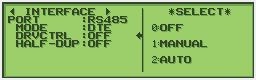
< RS-485 interface setting example >
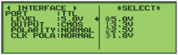
< TTL interface setting example >
Others
In addition to the high-speed function, it also has basic functions of protocol analyzer such as auto save function in which you can register captured data into SD card or USB flash for long time, file conversion into text file by text printing or utility software, search of specific data line, and remote control. You can also change the mode of the analyzer to standard firmware mode which support multi protocol by pressing both [SHIFT] and [0] keys when you turn on the power.