(For LE-8200A/8200)
OP-SB87FD
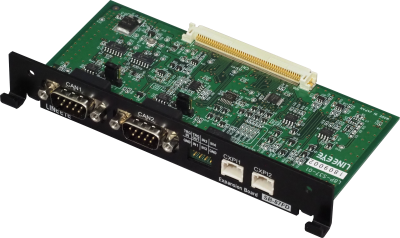

OP-SB87FD is an expansion board for LE-8200A/LE-8200 used for monitor/simulation of CAN (ISO 11898-1), CAN FD (ISO11898-1:2015), and CXPI (JASO D015). With this kit and the line state sheet, LE-8200A/LE-8200 works as a stand-alone type analzyer for CAN, CAN FD, and CXPI. The board supports development of CAN (used for automotive industry and other industries), CAN FD (next-generation standard of CAN providing more high-speed and communication capacity), and CXPI (invented in Japan to replace direct wirings) devices.
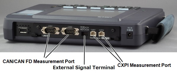
You can select the CAN FD/CAN or CXPI for each of the two measurement channels. When using in monitor mode, the 2 channels (CAN1(CAN FD/CAN) or CXPI1, CAN2(CAN FD/CAN) or CXPI2) can be used simultaneously.
The kit offers the monitor function in which you can monitor and save the communication data into measurement memory while displaying the monitored data in real time, and the simulation function in which you can trasmit/receive a test data.
The ID filter function and the trigger function make your development or evaluation more efficient. Also the kit can monitor the 4 lines external signals (as digital signal or analog signal) while measuring a communication data. It helps you to understand the relationship between the sensors or actuators such as motors and the communication data (such as command and response).
Usage image
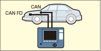
Easy setup for a CAN FD/CAN/CXPI analyzer !!
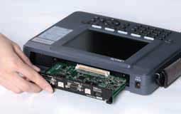
Once the CAN FD/CAN/CXPI measurement firmware is written to the analyzer, it can be used as a stand-alone analyzer that supports CAN FD/CAN/CXPI communication simply by replacing the interface board.
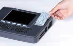
Exchanging the boards
The line state sheet for the measurement target is attached. It fits snugly into the line-state LED part of the analyzer.
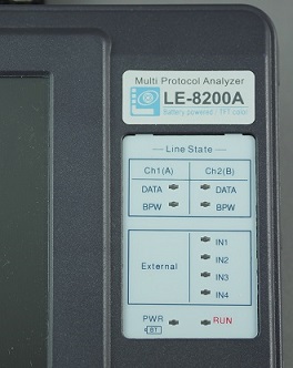
| Description | LED | Level |
|---|---|---|
| DATA | ON | Dominant |
| OFF | Recessive | |
| BPW | ON | Above 9V |
| IN1-IN4 | ON | Above 2.2V |
Operating Instructions
Connection
Use the attached Dsub9 pin monitor cable for CAN/CAN FD connection.
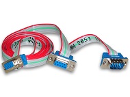
<CAN/CAN FD conncetion>
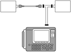
Use the attached 3-wire clip for CXPI connection.
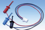
<CXPI conncetion>
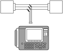
Monitor Function
CAN /CAN FD/CXPI simultanuous monitor
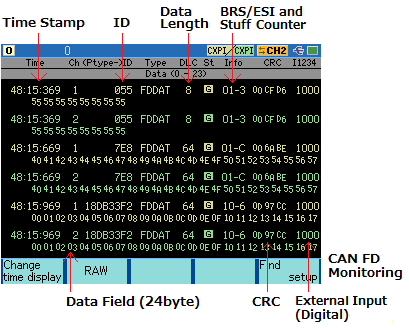
It can monitor CAN/CAN FD of 125kbps - 1Mbps(1Mbps - 5Mbps in high speed) and CXPI of 5kbps - 20kbps. It supports CAN (ISO 11898-1), CAN FD (ISO11898-1:2015 and Bosh original protocol), and CXPI (JASO D015). You can select the CAN FD/CAN or CXPI for each of the two measurement channels (Ch-1 and Ch-2). In the monitoring display, it displays the time stamp (resolution up to1us), frame ID, frame type, data length, CRC check result and value, and data field. For CAN FD it displays BRS bit, ESI bit value and for CAN FD (ISO) it displays the information of stuff counter field in addition to them .
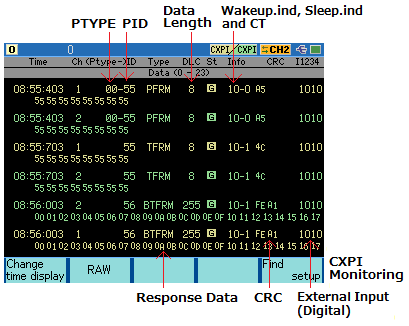
In the CXPI monitoring display it displays PTYPE, PID, frame type, Wakeup.ind bit, Sleep.ind bit, CT value, data length, CRC check result and value, and response data.
Frame type
| DAT | Standard/extended data frame of CAN |
| REM | Standard/extended remote frame of CAN |
| FDAT | Standard/extended data frame of CAN FD |
| ERR | Error frame of CAN/CAN FD |
| TFRM | Normal frame in event trigger method of CXPI |
| BTFRM | Burst frame in event trigger method of CXPI |
| PFRM | Normal frame in polling method of CXPI |
| BPFRM | Burst frame in polling method of CXPI |
| WUP | WAKEUP pulse of CXPI |
Analog monitor mode
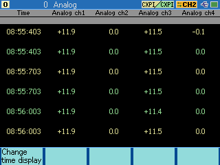
On-line mode measures voltage of four external signals at the time of monitoring CAN/CAN FD/CXPI data. Analog mode measures voltage of four external signals at specific sampling time (1ms to 10min) and can be used as an Analog data logger. Measurement data can be saved in the external memory as a text format.
Trigger Function
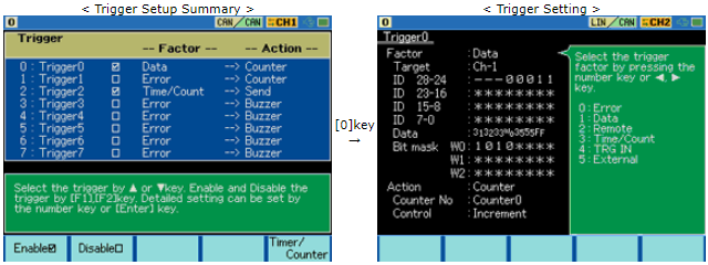
Up to 8 pairs of trigger condition and action can be specified. It can be used as a sequential trigger, which enables another trigger conditions as satisfied action of some trigger conditions. Therefore, it is useful for intermittent analysis of troubles.
FACTOR
| Contents | |
|---|---|
| ERROR | Executed the trigger by an error of the communciation. ACK: ACK error of CAN/CAN FD Error frame: CAN/CAN FD error frame Parity: CXPI parity error CRC: CRC error Framing: CXPI framing error |
| DATA | Executes the trigger when the specific data frame is received. Sets for the receiving channel, ID, and the contents of the data field. (Settable for DON'T CARE and a bit mask.) |
| REMOTE | Executes the trigger when the specific remote frame of CAN is received. Sets for the receiving channel and ID. (Settable for DON'T CARE and a bit mask.) |
| TM/CT | Executes the trigger when the timer or the counter reaches the value being set. SelectsTM0/TM1 or CT0/CT1. |
| TRG IN | Executes the trigger by status of TRG IN. |
| EXTERNAL | Executes the trigger by an external trigger input. Sets RISING or FALLING. |
| Contents | |
|---|---|
| BUZZER | Sounds for about 0.3 seconds. |
| STOP | Stops the measurement. Sets the time from the occurrence of the trigger to the stop of the measurement as OFFSET. * QUICK: Stops the measurement immediately. * BEFORE: Stops the measurement after taking some data following the trigger. * CENTER: Stops the measurement so that same amount of data is taken in before and after the trigger. * AFTER: Stops the measurement after taking in a large amount of data after the trigger. |
| SAVE | Save the data after the trigger point into the memory card (size is specified by Offset) |
| TIMER | Control the timer. Sets the kind of the timer and the contents of the control. * START: Starts the timer. * STOP: Stops the timer. * RESTART: Clears and restarts the timer. |
| COUNTER | Control the counter. Sets the kind of the counter and the contents of the control. * INCREMENT: Adds 1 to the counter. * CLEAR: Sets 0 for the counter. |
| TRIG SW | Controls another trigger state. * DISABLE: Sets invalid for the trigger. * ENABLE: Sets valid for the trigger. * CHANGE: Changes the trigger state. DTSABLE « ENABLE |
| SEND | Executes the control of the data which is set on the transmission data table. Sets transmission data table, the contents of the control (Transmit or Stop), and the time (RESPONSE) from the occurrence of the trigger to the control. (It is effective only at CAN.) |
| TRG OUT | Outputs Low pulse (1ms) to the external trigger (TRG OUT). |
Simulation
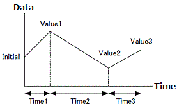
Some decode softwares of oscilloscope may be able to monitor CAN FD or CXPI but they cannot output a data and you may have difficulty in testing. By OP-SB87FD you can register up to 16 types of data frame (CAN FD) or remote frame (CAN, standard and extendedformat are supported) and transmit it by easy operation. The function helps you in the testing when you do not have communication partner. Also it can specify a part of frame as a sweep data and transmit it sweeping gradually with specified time interval from the initial value to third value. The function helps you to check how the CAN/CAN FD device behaves for the change of communication data.
For CXPI, you can select master/slave mode, event trigger method, and polling method. By making schedule function On, you can do the testing in which it transmits PID successively. It can sweep a part of frame data for CXPI too.
Support Logic Analyzer Analysis
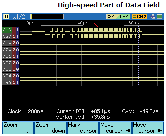
The logic analyzer operates at a sampling rate up to 100MHz, and able to analyze the timing of CAN/LIN signals and external signals. Waveform vision helps to identify hardware problems. You can also use it for education purposes.
Data Use
Search Function
It is possible to search the specific frame of Data and Time stamp.
Print Data
It is possible to print measured data and data tables.
Measurement result print out
*=[LE-8200A]=====[2018-02-11 3:21:16]=*
* Model     : LE-8200A                *
* Version   : 1.00                    *
* Extension : OP-SB87FD               *
* Serial No.: 99999999                *
* Start time: 2018-02-11 03:20:44     *
* Stop time : 2018-02-11 03:20:46     *
*-------------------------------------*
*  CH1 PROTOCOL: CAN FD(ISO)          *
*      BAUDRATE:250k                  *
*      BAUDRATE(DATA):2M              *
*  CH2 PROTOCOL: CAN FD(ISO)          *
*      BAUDRATE:250k                  *
*      BAUDRATE(DATA):2M              *
*=====================================*

----TM------CH------ID--TYPE--DLC-ST-INFO--CRC-----I1234-TRG
-----------------------------DATA---------------------------
20:45:608    1      099 FDDAT  64 G  01-A  053492   0001 [T]
000000000000000000000000000000000000000000000000
000000000000000000000000000000000000000000000000
00000000000000000000000000000000
20:45:608    2      099 FDDAT  64 G  01-A  053492   0001
000000000000000000000000000000000000000000000000
000000000000000000000000000000000000000000000000
00000000000000000000000000000000
20:45:609    1      099 FDDAT  64 G  01-A  053492   0001 [T]
000000000000000000000000000000000000000000000000
000000000000000000000000000000000000000000000000
00000000000000000000000000000000
20:45:609    2      099 FDDAT  64 G  01-A  053492   0001
000000000000000000000000000000000000000000000000
000000000000000000000000000000000000000000000000
00000000000000000000000000000000
20:45:610    1      099 FDDAT  64 G  01-A  053492   0001 [T]
000000000000000000000000000000000000000000000000
000000000000000000000000000000000000000000000000
00000000000000000000000000000000
20:45:610    2      099 FDDAT  64 G  01-A  053492   0001
CAN table print out
*=[LE-8200A]=====[2018-02-11 3:19:21]=*
* CAN DATA TABLE                      *
*=====================================*

--TYPE---------ID---DLC--REPEAT-INTERV-BSR-ENDIAN-SIZE-POS--INIT--TIME1-VALUE1--TIME2-VALUE2--TIME3-VALUE3
0:DATA          555          1    100  ON
55AA55AA55AA55AA55AA55AA55AA55AA55AA55AA55AA55AA55AA55AA55AA55AA
55AA55AA55AA55AA55AA55AA55AA55AA55AA55AA55AA55AA55AA55AA55AA55AA

1:DATA          000          1    100  OFF LITTLE   8   0      0      0      0      0      0      0      0

2:DATA          000          1    100  OFF

3:EXDATA   00000000      99999  99999  OFF LITTLE  16   63  65535 999999 -32768 999999  65535 999999 -32768
8888888888888888111111111111111188

4:DATA          000          1    100  OFF

5:DATA          000          1    100  ON

6:DATA          077          1    100  OFF
0000000000000000000000000000000000000000000000030000000000000000
0000000000000000000000000000000000000000000000000000000000000000
CXPI table print out
*=[LE-8200A]======[2018-02-11 3:21:37]=*
* CXPI DATA TABLE                      *
*=====================================*

--ENABLE-TYPE----ID-WAKE-SLEEP-CT-CTINC-ENDIAN-SIZE-POS--INIT--TIME1-VALUE1--TIME2-VALUE2--TIME3-VALUE3
0:  *    NORMAL  55    1     0  0  OFF  LITTLE   8   0  65535 999999      0      0      0      0      0
55AA55AA55AA55AA55AA55AA55AA55AA55AA55AA55AA55AA55AA55AA55AA55AA
55AA55AA55AA55AA55AA55AA55AA55AA55AA55AA55AA55AA55AA55AA55AA55AA
55AA55AA55AA55AA55AA55AA55AA55AA55AA55AA55AA55AA55AA55AA55AA55AA
55AA55AA55AA55AA55AA55AA55AA55AA55AA55AA55AA55AA55AA55AA55AA55AA
55AA55AA55AA55AA55AA55AA55AA55AA55AA55AA55AA55AA55AA55AA55AA55AA
55AA55AA55AA55AA55AA55AA55AA55AA55AA55AA55AA55AA55AA55AA55AA55AA
55AA55AA55AA55AA55AA55AA55AA55AA55AA55AA55AA55AA55AA55AA55AA55AA
55AA55AA55AA55AA55AA55AA55AA55AA55AA55AA55AA55AA55AA55AA55AA55

1:       NORMAL  7F    1     0  0  OFF
FF00F000

2:       BURST   55    1     0  0  OFF
55AA55AA55AA55AA55AA55AA55AA55AA55AA55AA55AA55AA55AA55AA55AA55AA
55AA55AA55AA55AA55AA55AA55AA55AA55AA55AA55AA55AA55AA55AA55AA55AA
55AA55AA55AA55AA55AA55AA55AA55AA55AA55AA55AA55AA55AA55AA55AA55AA
55AA55AA55AA55AA55AA55AA55AA55AA55AA55AA55AA55AA55AA55AA55AA55AA
55AA55AA55AA55AA55AA55AA55AA55AA55AA55AA55AA55AA55AA55AA55AA55AA
55AA55AA55AA55AA55AA55AA55AA55AA55AA55AA55AA55AA55AA55AA55AA55AA
55AA55AA55AA55AA55AA55AA55AA55AA55AA55AA55AA55AA55AA55AA55AA55AA
55AA55AA55AA55AA55AA55AA55AA55AA55AA55AA55AA55AA55AA55AA55AA55

3:       BURST   7F    1     0  0  OFF
55

4:       BURST   01    1     0  0  OFF

5:       NORMAL  01    1     0  0  OFF

6:       NORMAL  01    1     0  0  OFF