(For LE-8600X/LE-8500X series)
SB-C2AN

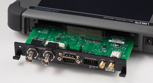
SB-C2AN is an interface expansion kit for the LE-8500X/LE-8600X series for CAN (ISO 11898-1), CAN FD (ISO11898-1:2015) and analog measurements. It functions as both a CAN analyzer and an analog measuring instrument and provides powerful support for in-vehicle tests that require multiple analog information along with communication data.
Applicable analyzers: LE-8600X serias and LE-8500X series
Feature
●By just one unit works as both a CAN analyzer and a frequently used analog measurment tool.
●Supports CAN FD up to 5Mbps
●Real-time monitoring of two communication lines simultaneously
●Reliably catch specific frames using ID filters and trigger functions
●Periodic data-transfer simulation that can mix CAN FD and CAN communication frames
●High-speed analog waveform measurement up to 100M samples/sec
●Record 8 channels of voltage along with communication data for a long time using the included analog measurement pod.
●CAN translation function that allows graph drawing simultaneously with analog measurement values.
●High-precision analog measurement and temperature measurement are also available optionally.
●GPS location information record compatible with submeter-level positioning reinforcement service
Easy setup
The firmware is preinstalled, and by simply replacing the interface board, it can be used as a standalone analyzer that supports in-vehicle communication and analog measurement.
Simultaneous measurement and real-time display of CAN, analog signals, and GPS data
Continuous measurement recording and real-time display of 2-channel CAN/CANFD communication data, up to 8 analog signals, and GPS positioning data with time stamps are possible.
Analog signals can be input via an analog pod connected to the extended analog measurement port or from the high-speed analog measurement port.
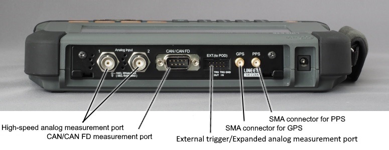
CAN (CAN FD) measurement port pin assignment
Dsub9 pin connector
| Pin | Signal | Meaning |
|---|---|---|
| 1 | CAN2 Low | CAN/CANFD Ch2 bus signal (Low) |
| 2 | CAN1 Low | CAN/CANFD Ch1 bus signal (Low) |
| 3 | GND | Sginal ground |
| 4 | - | |
| 5 | - | |
| 6 | GND | Sginal ground |
| 7 | CAN1 High | CAN/CANFD Ch1 bus signal (High) |
| 8 | CAN2 High | CAN/CANFD Ch2 bus signal (High) |
| 9 | - |
External trigger/extended analog measurement port (pin header 10 pins 2.54mm pitch)
This connector connects the included analog pod OP-8AH and optional analog pod OP-8AT. You can also use the TRG.IN and TRG.OUT terminals to input and output external triggers.
Connection
Connect the analyzer's measurement port to the line to be measured using the attached cable.
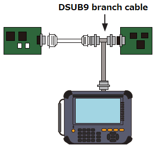
With the optional OBD2-DSUB9 cable, you can easily connect the Ch1 to an OBD2 connector of a car.
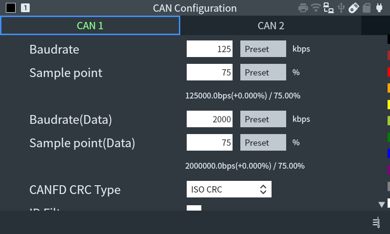
Supports CAN FD up to 5Mbps
It can execute the online monitoring recording CAN/CAN FD communication frames with a communication speed of 20kbps to 5Mbps in the capture memory with time stamps of the resolution of 1µ second. Communication data is acquired by the measurement FPGA, so unlike CAN monitors using CAN controller ICs that cannot display ACK error frames, all communication frames are accurately captured and displayed.
[ CAN/CAN FD communication condition setting ]
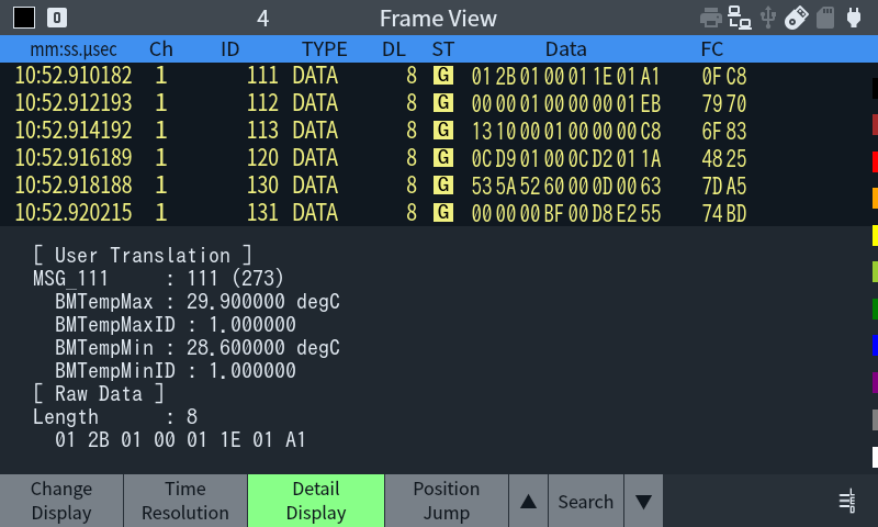
[ CAN/CAN FD monitor screen ]
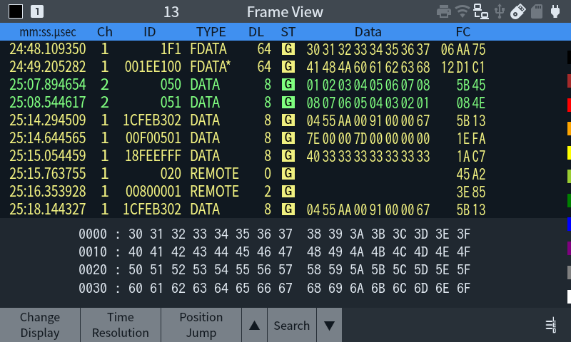
You can check the timestamp, channel, ID, communication frame type, data length (DLC), communication frame status (St), data (in hexadecimal), and CRC value (FC).
Frame type (Type) display
| Data | Data frame | Remote | Remote frame | Error | Error frame | FData | CAN FD frame with BRS=0, ESI=0 | FData! | CAN FD frame with BRS=0, ESI=1 | FData* | CAN FD frame with BRS=1, ESI=0 | FData*! | CAN FD frame with BRS=1, ESI=1 |
Frame status (St) display
| G | Normal frame |
| A | ACK error |
| F | Form error |
| C | CRC error |
| E | Error frame |
Catch specific frames using ID filters and trigger functions
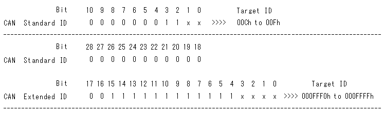
Record only the specified data with ID filter
Data of various IDs flow on a line that connects many nodes. By setting an ID filter and narrowing down the IDs of communication nodes to be investigated, analysis efficiency will be greatly improved.
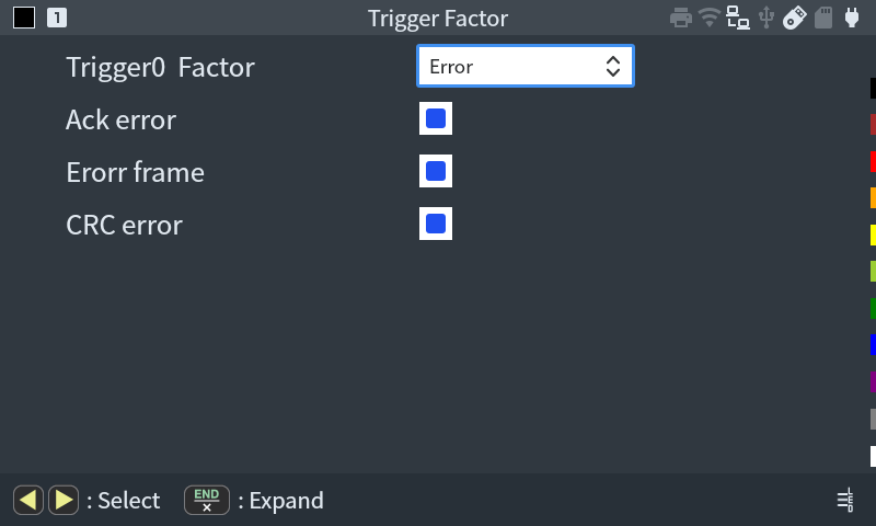
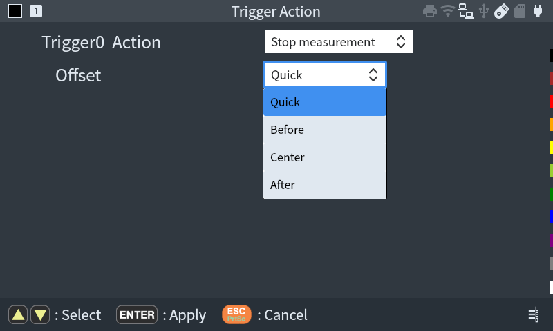
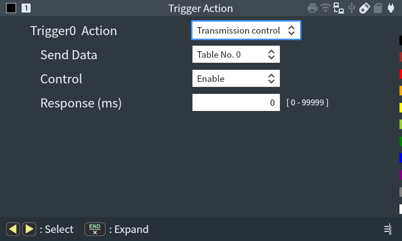
Trigger function
Measurement can be performed by specifying up to 8 sets of conditions and measurement operations after the conditions are met. It can be used as a sequential trigger to automatically stop measurement when a specific data frame is received, or to enable another trigger condition when one trigger condition is met, making it extremely useful for intermittent failure analysis.
[ Trigger summary screen ]
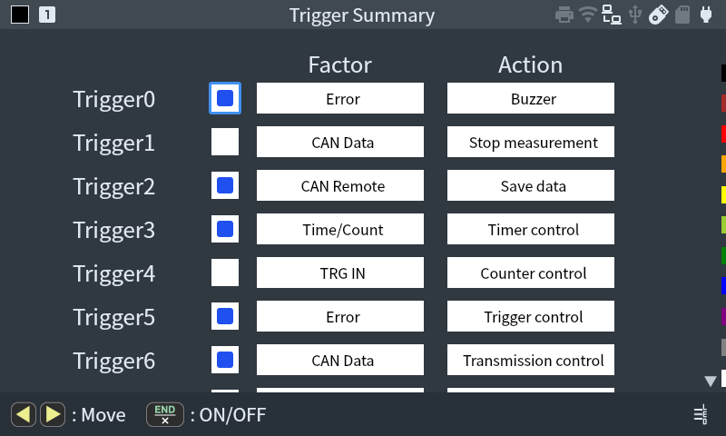
Communication error occurrence, specific data reception, remote frame reception, timer/counter value matching, and external trigger input can be specified as the trigger factor.
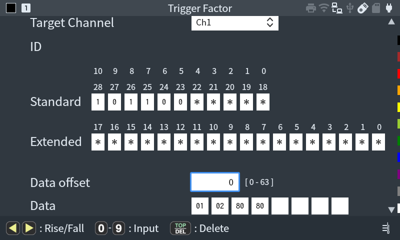
When a trigger is met, the following actions can be specified: buzzer sound, measurement stop, data saving before and after the trigger, timer/counter operation, enable/disable specified trigger, CAN frame transmission, external trigger output, etc.
Simulation function ideal for communication partners in the early stages of development
When the target device is not available at the early stage of development, this device can act as a communication partner for the device under test and send CAN/CAN FD test frames.
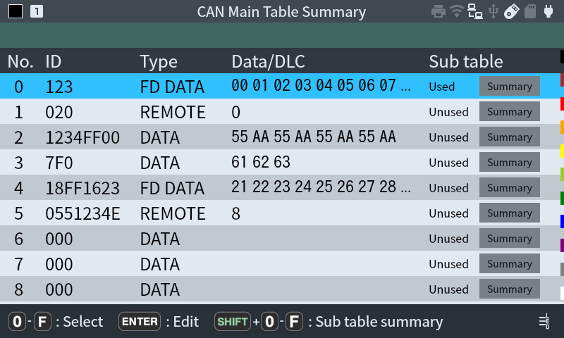
Periodic transfer simulation that can mix CAN FD and CAN communication frames
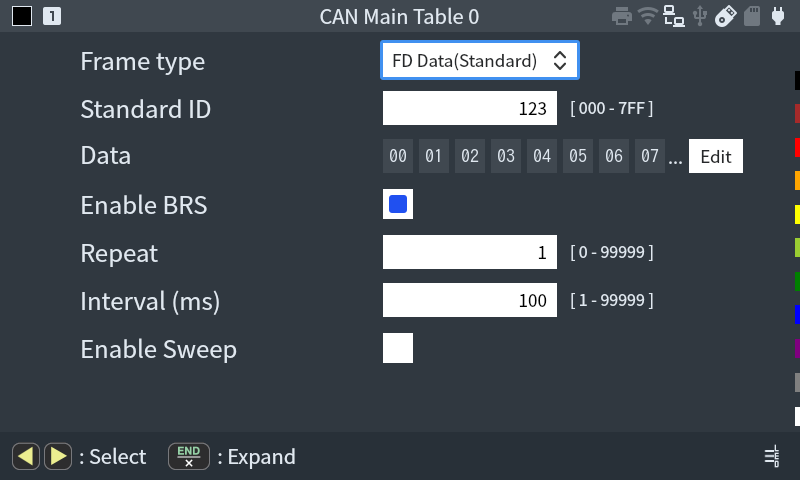
The 16 types of main data tables correspond to the [0]-[F] keys on the main unit and you can send test frames with one touch. Pre-registered data frames and remote frames in the standard format / extended format can be sent simultaneously at any cycle.
[ Main table summary display ]
[ Main table editing screen ]
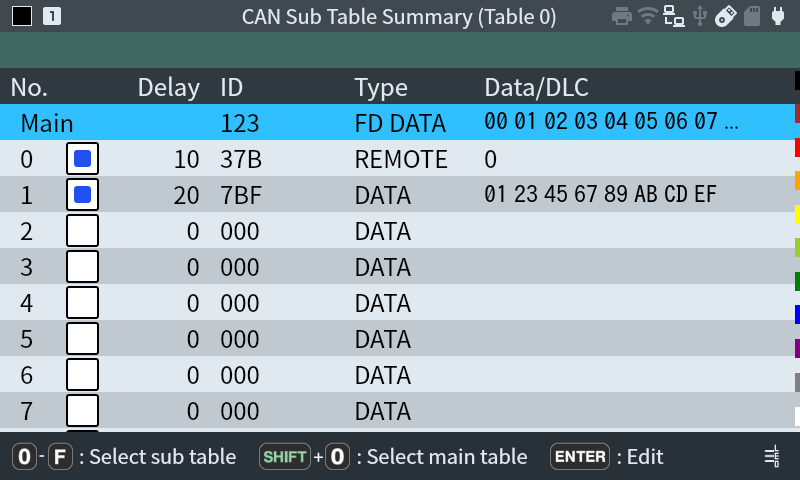
Sweep function that automatically changes part of communication data at an arbitrary rate of change
It can specify a sweep that automatically changes part of the communication data at an arbitrary rate of change. This is useful when checking how the behavior of the actuator under test changes in response to changes in communication data.
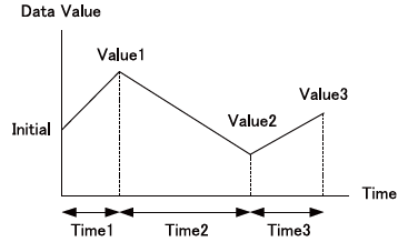
[ Sweep setting ]
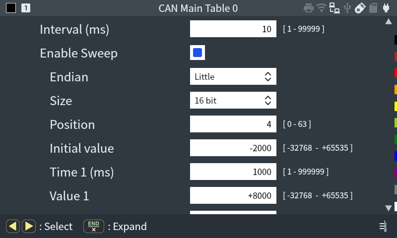
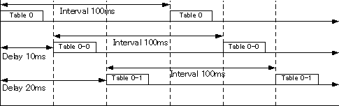
A total of 272 types of test frame transmission using sub-tables
Each main data table has 16 sub-tables, allowing group transmission with a single keystroke. In addition to the same settings as the main table, the sub-table has additional transmission ON/OFF settings and "delay time" settings, and depending on the settings, periodic transmission as shown below is possible.
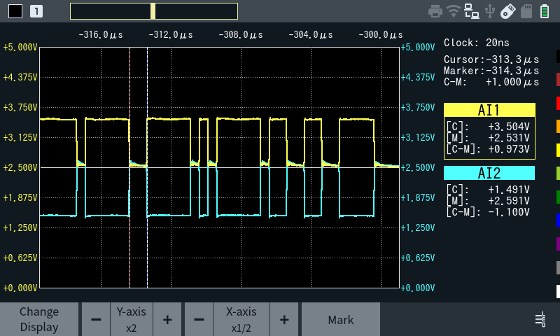
High-speed analog waveform measurements up to 100M samples/sec
The 2-channel analog voltage waveform measurement function supports up to 100M samples/sec and ±24V. You can easily observe detailed waveforms at sight without bringing out heavy general-purpose measuring instruments.
[ Connection image of high-speed analog signals ]
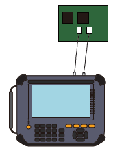
In addition to voltage rising/falling edges, waveforms can be acquired by CAN communication measurement triggers. This is useful for investigating the cause of rare problems. In addition, it can be connected internally to the differential communication line of the CAN communication measurement port (Ch1), allowing detailed observation of CAN (CAN FD) communication signals without pulling out a line for a probe. It is ideal not only for investigating hardware problems but also for educational purposes related to data communications.
Analog measurement (logger) function that records analog voltage for long periods of time along with communication data
8ch voltage logger with attached analog pod
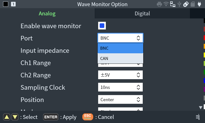
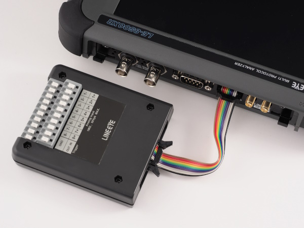
The 2ch input of the BNC analog measurement port can be used for analog measurement even on a standalone board, but by connecting the included analog pod "OP-8AH" to the expansion pod connector, the analog measurement function is further enhanced and it can be used as an 8ch voltage logger.
[ Connection image of high-speed analog signals measurement ]
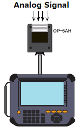
Connect the cable and OP-8AH to the expansion pod connector EXT.(to POD).
Input up to 8 channels of analog signals to OP-8AH. GND is common.
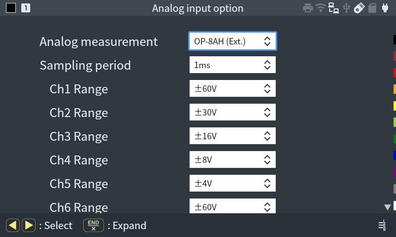
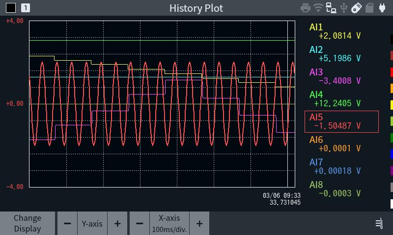
The measurement range can be set to a maximum of +-60V, and the measurement cycle can be set to a maximum of 62.5µ seconds (16kSPS). Measured values are displayed graphically in real time.
[ OP-8AH measurement setting ]
[ [OP-8AH graph display ]
Can be expanded more with optional measurement pods
The optional analog pod OP-8AT supports not only voltage but also 4-20mA current measurement and temperature measurement using thermocouples. Analog signals with different ground potentials can be measured with high accuracy [e.g. ±(0.05% rdg + 2mV): 10V range].
[ Connection image of analog measurement pod OP-8AT (optional) ]
[ Temperature and voltage measurement example by OP-8AT ]
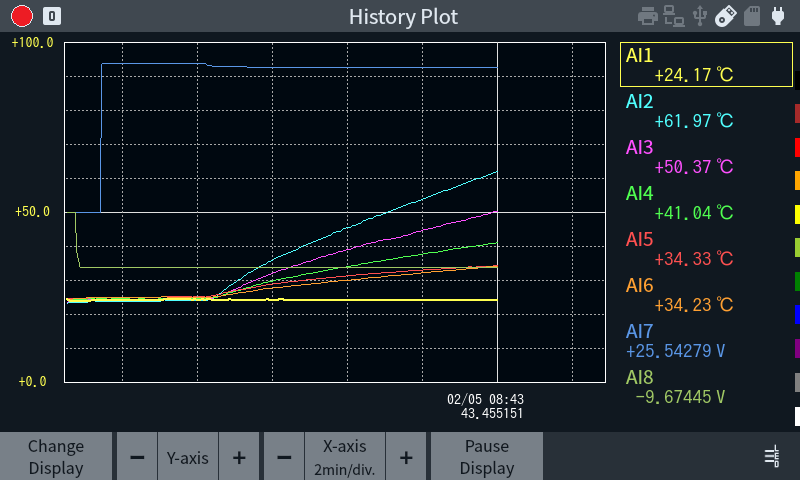
CAN translation function that allows graph drawing simultaneously with analog measurement values.
By reading DBC files (.dbc), which are widely used to describe CAN translation definitions, you can translate and display information such as physical quantities contained in CAN / CAN FD frames.
In addition, translated values can be displayed in graphs in real time. Up to 8 signals can be drawn simultaneously in combination with the normal analog measurement graph display (either BNC analog measurement port / measurement pod OP-8AH / measurement pod OP-8AT).
<Example of translation display>
<Example of mixed graph display of analog and translated values>
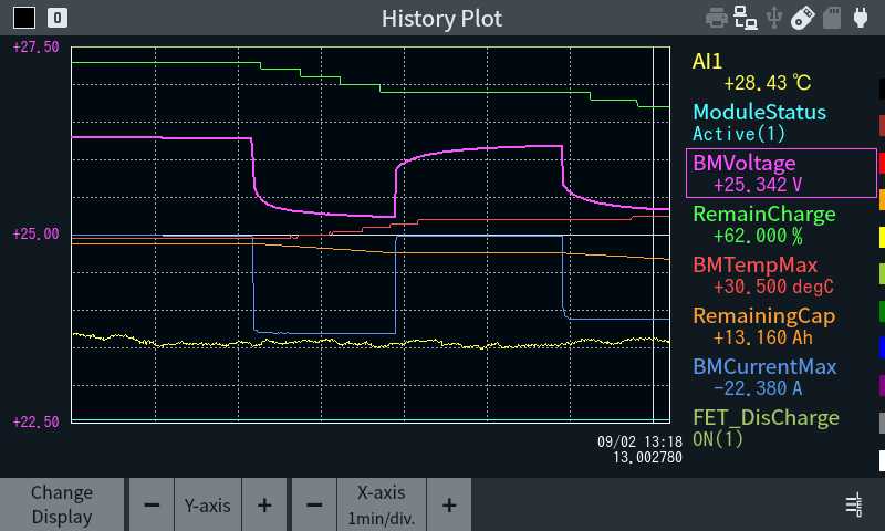
The physical quantities included in the CAN/CAN FD frame and analog measured values such as voltage, current, and temperature can be confirmed and compared in real time on the main display, making it ideal for in-vehicle testing, etc.
Long-term recording that can be rolled back to the point of communication failure
CAN/CAN FD communication measurement data and analog measurement (logger) function data are recorded in the built-in 1GB large-capacity capture memory. You can choose between a ring buffer mode that allows endless recording and a fixed buffer mode that automatically stops when the memory is full. Additionally, using the auto-save function, you can continuously save the contents of the capture memory being monitored in specified file size units to a large-capacity external storage device. It will be useful in solving unexplained communication failures that occur only rarely.
| Estimated continuous recording time*1 | ||
|---|---|---|
| Built-in memory only | 64Gbyte USB flash memory*2*3 | 500GB SSD*2*3 |
| Approximately 1 hour | Approximately 70 hour | Approximately 23 days |
CAN FD communication data: Observe 64-byte frames every 1ms each for Ch1 and Ch2
Analog measurement data: Recording 8 channels of analog voltage at a 1ms cycle using OP-8AH
Does not guarantee the operation of all USB memory and USB connected SSDs.
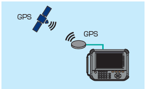
Location information recording compatible with submeter-level positioning reinforcement services
By connecting an optional GPS antenna, location information can also be recorded. It can be recorded for long periods of time together with CAN (CAN FD) communication data and analog measurement data, making it useful for driving tests, etc.
Multi-GNSS (GPS, QZSS, GLONASS, Galileo, BeiDou) compatible. It supports Michibiki (Quasi-Zenith Satellite System/QZSS) submeter-level positioning augmentation service (SLAS), enabling highly accurate positioning.
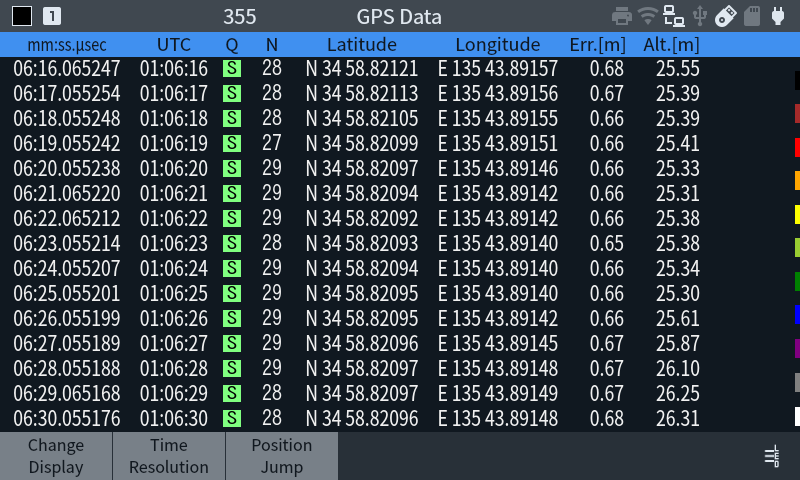
The time stamp of this device at the recording time (for comparison with communication data, etc.), UTC time, reception status, number of satellites used for positioning, latitude, longitude, horizontal estimation error, and changes in altitude above sea level are displayed in real time on the measurement screen.
Display of reception status (St)
| G | Valid positioning data |
| S | Valid positioning data, SLAS or SBAS correction enabled |
| T | Data valid only for time |
| I | No valid data |
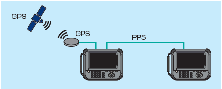
Timestamp that can be synchronized with GNSS (PPS) signals
Since the PPS signal for time synchronization can be output from this unit to which the GPS antenna is connected, by connecting a second analyzer with an SMA coaxial cable (sold separately), simultaneous measurement of two analyzers with synchronized time stamps is possible. A different type of measurement board can be used as the second unit, for example, synchronous measurement with the LE-8500X-SE, which supports in-vehicle LAN communication, is possible.
[ GPS connection image ]
[ Simultaneous measurement image of two devices using PPS signal ]
Save and print measurement report in a snapshot or text/CSV format
By pressing [SHIFT] + [ESC], you can take a screenshot of the screen display image of the measurement results / setting conditions and save it as a PNG file. You can also convert measurement data to a text file on the instrument and save it to a storage device, which is useful for making reports of test results. Analog measurement data can also be saved in CSV format. GNSS positioning data can also be saved in KML format. In addition, by connecting a dedicated printer, you can continuously print out a specified range of measurement data or print out a hard copy of the screen display image, which can be used as a recorded memo on site.
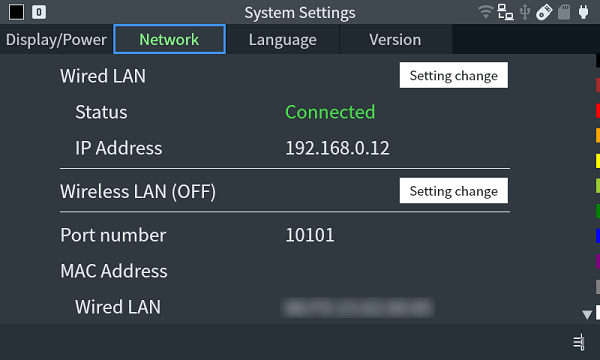
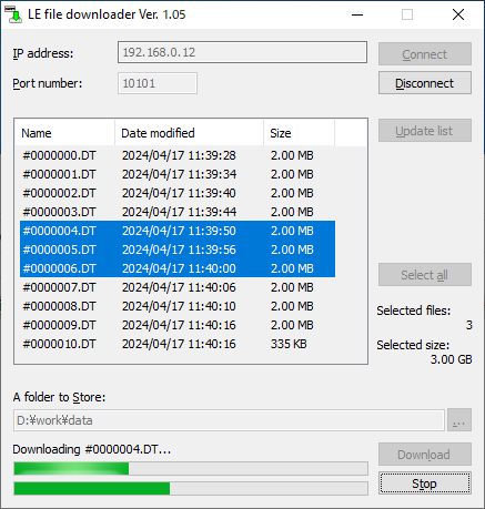
Transfer communication log files to your PC while continuing measurements.
Using the "LE File Downloader lefiledownload (V1.04 or later)," you can transfer communication log files saved to a storage device using the autosave function to your PC via LAN or Wi-Fi. Execute the autosave function on the analyzer set up in the field, then transfer communication log files with timestamps around the time of the communication failure to your PC. Then, use text conversion software to convert the files to readable format and analyze them.
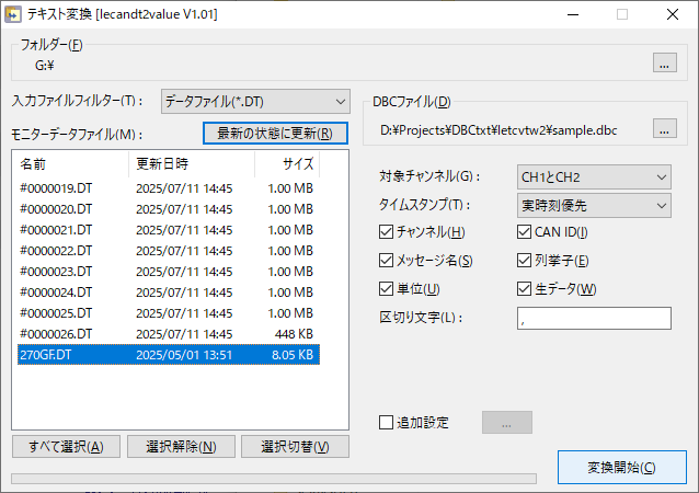
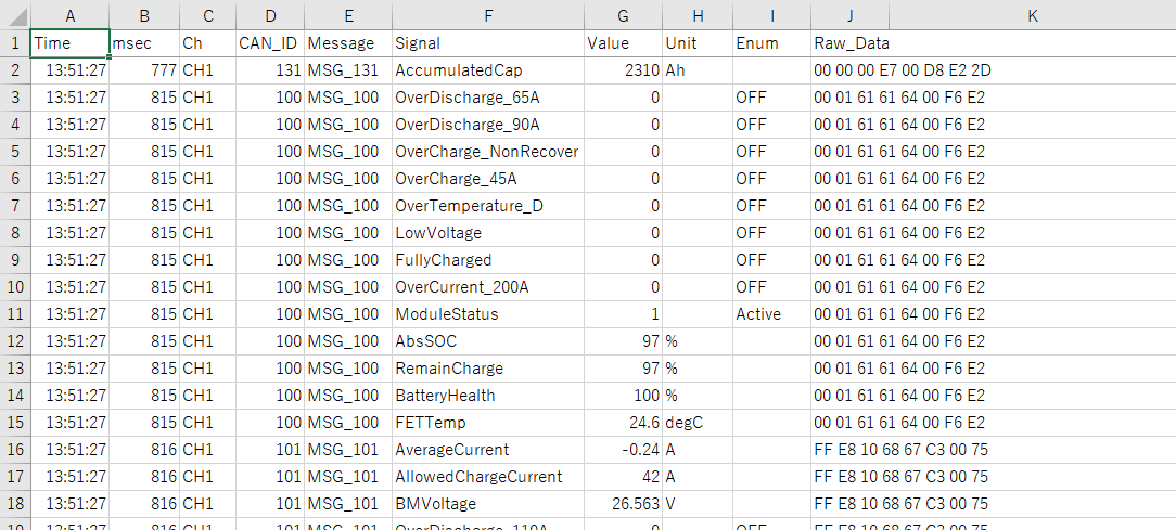
CAN communication data translation (numerical conversion) software for convenient post-analysis on a PC has been released
CAN communication log data saved to your computer via the LE File Downloader or USB memory can be converted into physical quantities and output in CSV format using the CAN data numeric conversion software lecandt2value. This converts the data into DBC files (.dbc), which are widely used to describe CAN translation definitions.
CAN communication data logs can be converted to Pcap format
Measured CAN / CAN FD communication data can also be converted to Pcap format, which can be used with free software such as Wireshark. Pcap conversion is available via file output from the device's controls, and also with the text conversion software.
