PRODUCT
Expansion kit for CAN/High-speed Analog
(For LE-8600X/LE-8500X series)
(For LE-8600X/LE-8500X series)
SB-C2AN

Specification
| Applicable analyzers | LE-8600X series, LE-8500X series |
|---|---|
| CAN FD/CAN measurement port | ISO11898-1:2015 and ISO11898 compliant (Dsub 9 pin male connector, inch screw #4-40) |
| Measurement channels | 2 channels can be measured simultaneously |
| Transceiver | MCP2542FD (Microchip) equivalent |
| High-speed analog measurement port |
Number of channels: 2, built-in 12bit resolution/100Msps high-speed ADC (BNC connector x 2) |
| Input impedance withstand voltage |
1MΩ, 50Ω can be selected, withstand voltage: max.±30Vpk (at 1MΩ), max.±6Vpk (at 50Ω) |
| Input range | ±24V, ±12V, ±5V, ±2.5V |
| External trigger/ Extended analog measurement port |
External trigger input/output, expansion analog pod connection port (MIL10 pin connector) |
| Analog pod OP-8AH (standard equipment) |
8 channels, built-in 24-bit resolution ADC, screwless terminal block |
| Input impedance withstand voltage |
1MΩ, withstand voltage: max.±65Vpk, GND common between channels, non-isolated |
| Input range | ±60V, ±30V, ±16V, ±8V, ±4V |
| Measurement accuracy*1 | ±60V range, ±30V range, ±16V range : ±(0.1% rdg + 3mV) ±8V range, ±4V range : ±(0.1% rdg + 2mV) |
| Analog pod OP-8AT (optional) | Number of channels: 8, 24-bit resolution, built-in high-precision ADC, screwless terminal block |
| Input impedance voltage resistance |
1MΩ, withstand voltage: max±50Vpk, channel-to-channel isolation 350V (AC peak/DC) |
| Signal isolation voltage | Between analog input and analyzer 1500V (AC peak/DC) 350V (AC peak/DC) between each channel of analog input |
| Input range*2 | ±30V, ±10V, ±1V, ±100mV, 0-20mA, temperature K, J, T, E, N, R, S, B type thermocouple compatible |
| Measurement accuracy※3 | ±30V range ±(0.05% rdg + 3mV), ±10V range ±(0.05% rdg + 2mV), ±1V range ±(0.05% rdg + 0.2mV),
±100mV range ±(0.05% rdg + 50µV), 0-20mA current range ±0.05% FS, Temperature range: See below table |
| Monitor function | Displays and records ID, type, content, error, and CRC of CAN/CAN FD communication frame. CAN/CAN FD sampling point (60% to 90%) can be set. |
| Extended protocol | CAN-FD(ISO/Non-ISO), CAN2.0B, DeviceNet※4 |
| Communication speed | CAN: 20kbps to 1Mbps CAN FD: 20kbps ~ 1Mbps BRS ON data field 1Mbps ~ 5Mbps (Arbitrary speed setting is available) |
| Capture memory | Uses the analyzer's capture memory※5, auto-save to external storage is available |
| ID filter | Only the specified standard/extended ID (bitmask can be specified) frame can be recorded for each channel |
| Error checking function | CAN /CAN FD: ACK error, form error, CRC error, error frame |
| Timestamp | Records frame reception time (time resolution 1 μs) Can switch display between real time (year, month, day, hour, minute, second, μsecond), elapsed time from start of measurement, and difference time from previous frame. GNSS/GPS signal or Time synchronization via external PPS signal is possible |
| Trigger function | OR operation and sequence operation are possible by specifying up to 8 sets of conditions and operations |
| Trigger condition | Error (non-ACK, ERROR frame, CRC), specified data frame (channel, ID, data, data offset, data bit mask), specified remote frame (channel, ID), timer match, counter match, external trigger input |
| Trigger action | Stop measurement, save measured data to SD card/USB storage, timer control, counter control, send specified data, buzzer, enable/disable trigger conditions, external trigger output |
| Simulation function | Transmission test of pre-registered test frames (CAN/CAN FD: 272 types) is possible. Caan automatically increase/decrease (sweep) the specified position data in the data field※6. Multiple frames selected by key operation can be sent at each specified period (the number of transmissions can also be specified). |
| Search function | Search for error, frame with specified ID and data (up to 8 characters, don't care and bit mask can be specified, offset from the beginning of frame to judgment data can be specified), real time timestamp in specified range, trigger match data can be searched and counted, mark jump to frame pointer possible |
| Analog measurement (Analog logger) function |
Records the analog value of the specified analog measurement port at specified intervals and displays graph/numeric values |
| Recording mode | It is possible to select between analog independent measurement and parallel measurement with CAN/CAN FD monitor function, and the related display of communication data and analog values based on time stamps is possible. |
| Recording cycle | When selecting high-speed analog measurement port: 10µ seconds to 100m seconds, when selecting analog pod OP-8AH: 62.5µ seconds to 100m seconds, when selecting analog pod OP-8AT: 10m seconds to 1 minute ※7 |
| Analog waveform monitor (oscilloscope) function |
Measure the voltage of the CH1 differential signal line of BNC connector x2 or CAN/CANFD at the sampling clock cycle and display the waveform |
| Sampling clock | 20KHz to 100MHz (12 steps) |
| Sampling memory | Maximum 32,768 sampling |
| Trigger mode | Measurement can be stopped according to the position setting after trigger conditions are met, and waveform display can be selected repeatedly after trigger conditions are met |
| Trigger condition | Voltage level (rising/falling) of specified input channel, match of specified trigger condition of online monitor function |
| Trigger position | Before (emphasizes before the trigger), Center (center), After (emphasizes after the trigger) |
| Other features | Enlarged/reduced display, voltage/time measurement function between cursors |
| Digital waveform monitor (Logic analyzer) function |
Measures logical changes in CAN/CAN FD communication signal lines at sampling clock cycles and displays waveforms |
| Sampling clock | 1KHz~100MHz (16 steps) |
| Sampling memory | Maximum 4,096 sampling |
| Trigger mode | You can choose to wait for the trigger condition immediately after measurement, or wait for the trigger condition after the sampling memory is fully recorded |
| Trigger condition | Logical state match of CAN/CAN FD communication signal line, match specified trigger condition of online monitor function |
| Trigger position | Before (emphasizes before the trigger), Center (center), After (emphasizes after the trigger) |
| Trigger pass count | You can specify the number of times (0 to 9999) to pass (ignore) trigger condition matching |
| Other features | Enlarged/reduced display (10 steps), time measurement function between cursors, signal line swapping function, signal status search function |
| GPS function | Equipped with SMA (female) connector for active GPS antenna connection Timestamps can be synchronized to UTC time with high precision Can record and display latitude, longitude, height above sea level, etc. in parallel with CAN/CAN FD communication data and analog measurement values. QZSS SLAS (submeter class positioning augmentation service) compatible Positioning data can be output in kml format. |
| Translation function※8 | DBC files can be read to display the translation of CAN frames. The translation results of the selected signal can be displayed in a graph together with the analog measurement value. |
| Other features | Auto save function, automatic backup function, automatic time specified RUN/STOP function, file management function, text conversion function (txt format, csv format), printout function |
| Temperature range | Operation: 0 to 40℃ Storage: -20 to 50℃ |
| Humidity range | 20 to 85%RH (no condensation) |
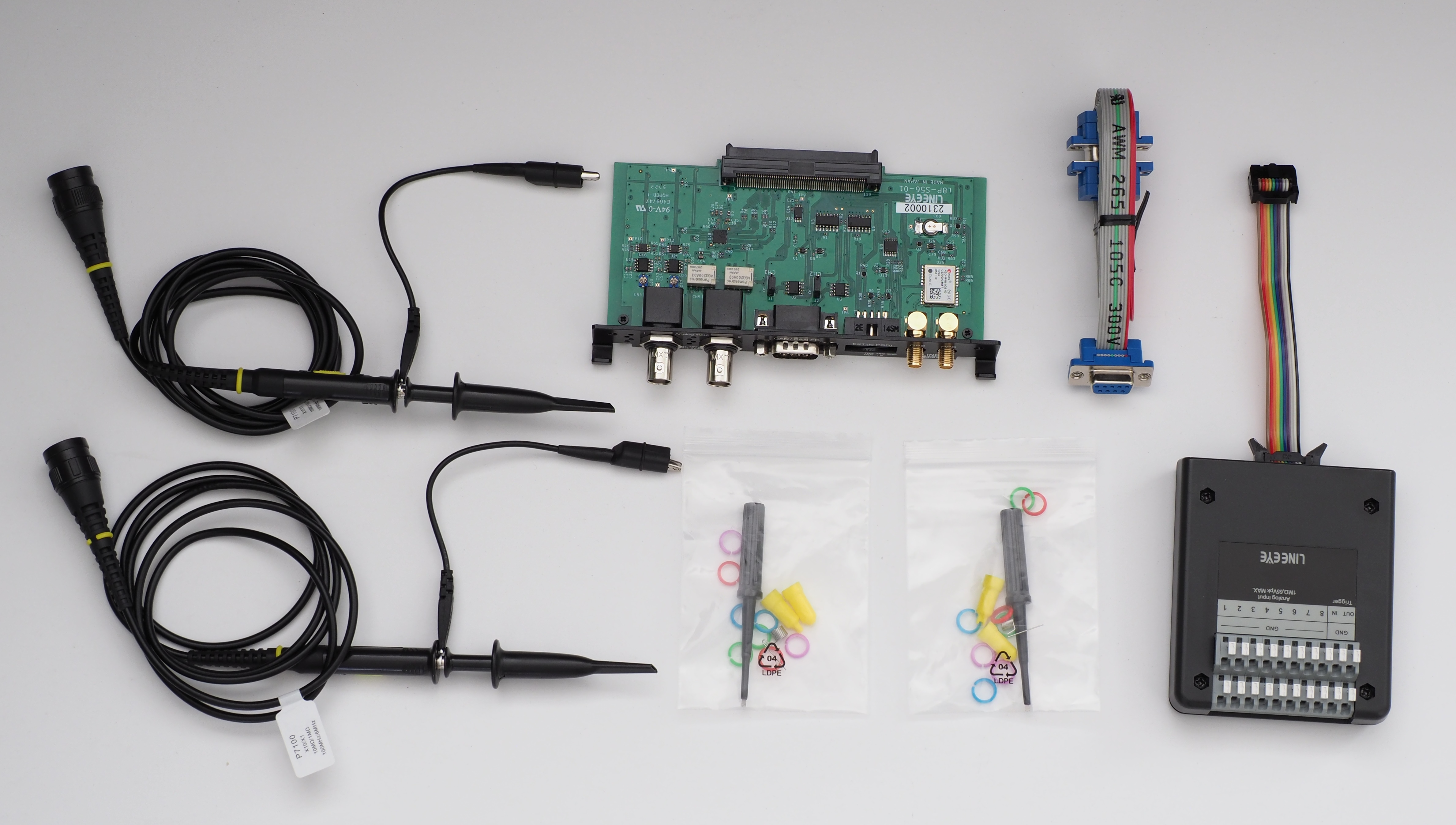
| Components | Interface sub board 1 piece, DSUB9 pin branch cable 1 piece, passive probe 2 pieces, high-speed high voltage analog measurement pod (OP-8AH) 1 piece, pod connection cable 1 piece, quick start guide, warranty card |
*1: rdg represents the accuracy of the reading.
*2: For the 0-20mA range, an external current detection resistor (250Ω or 50Ω, accuracy±0.1% or less) is required on the input terminal block. is.
*3: rdg represents the accuracy for the reading value, and FS represents the accuracy for the full scale of the range. Current accuracy does not include external resistance errors.
*4: Only raw data can be displayed.
*5: The main body capture memory is consumed as a recording area for CAN/CAN FD communication data, analog measurement values, and GPS data.
*6: Endianness, initial value and 3 levels of target values, and time to reach the target can be specified.
*7: The 10ms cycle of analog pod OP-8AT is only possible when the number of measurement channels is 1.
*8: System version 1.11 or later is required.
<Standard Accessories>
| Compatible thermocouple | K, J, T, E, N, R, S, B type | |
|---|---|---|
| Measurement temperature range |
K type: -200℃ ~ 1370℃ J type: -210℃ ~ 1200℃ T type: -200℃ ~ 400℃ E type: -200℃ ~ 1000℃ N type: -200℃ ~ 1300℃ R type: 0℃ ~ 1760℃ S type: 0℃ ~ 1760℃ B type: 400℃ ~ 1800℃ |
|
| Cold junction compensation | Internal compensation, external compensation switchable | |
| Disconnection detection function | On/off switchable (applied current: approx. 180nA) | |
| Measurement accuracy*1 | K type |
-50℃ ~ 1370℃ : ±(0.05% rdg + 1.0℃) -200℃ ~ -50℃ : ±(0.05% rdg + 2.0℃) |
| J type |
-50℃ ~ 1200℃ : ±(0.05% rdg + 0.8℃) -210℃ ~ -50℃ : ±(0.05% rdg + 1.6℃) |
|
| T type |
-50℃ ~ 400℃ : ±(0.05% rdg + 1.0℃) -200℃ ~ -50℃ : ±(0.05% rdg + 2.0℃) |
|
| E type |
-50℃ ~ 1000℃ : ±(0.05% rdg + 0.6℃) -200℃ ~ -50℃ : ±(0.05% rdg + 1.2℃) |
|
| N type |
-50℃ ~ 1300℃ : ±(0.05% rdg + 1.5℃) -200℃ ~ -50℃ : ±(0.05% rdg + 3.0℃) |
|
| R type S type |
400℃ ~ 1760℃ : ±(0.05% rdg + 3.5℃) 0℃~400℃: ±(0.05% rdg + 6.0℃) |
|
| B type |
800℃ ~ 1800℃ : ±(0.05% rdg + 4.0℃) 400℃ ~ 800℃ : ±(0.05% rdg + 7.5℃) |
|
| Cold junction compensation accuracy*2 | ±1.0℃ | |
*1: Accuracy at ambient temperature of 18 to 28°C and after 20 minutes after power on, does not include thermocouple error.
If the above ambient temperature range is exceeded, add 1/20 of each error value for every 1°C.
If the above ambient temperature range is exceeded, add 1/20 of each error value for every 1°C.
*2: In environments where a part of the measurement pod is locally heated or cooled, cold junction compensation accuracy cannot be guaranteed.