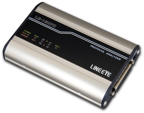
LE-150PR
●2-way operation of PC-connected protocol analyzer / logger
●Remote measurement from PC by Wi-Fi connection
●Supports measurement of arbitoral speed (4 significant digits)
●Continuously recording for a long time on the HDD of PC or the SD card in the unit
●Power failure countermeasure circuit to ensure recording to SD card
●Unattended measurement with specified time by RTC (real-time clock)
●Trigger function to control external signal output terminal and user-defined LED
●Simulation function that can send registered character strings by simple operation
●Small palm-sized body
LE-150PR is a lightweight communication protocol analyzer has a Data Logger function to record data in the SD card for long hours. It is an entry model designed for Asynch communication. While succeeding all the excellent cost-performance of LE-150PS, LE-150PR can be connected by Wi-Fi (available only in Japan, USA, Canada, and EU).
This model is discontinued. The successor is LE-150PF.


Two Types of Operations Depending on Usage Situation.
This device can be used as a PC-connectable Protocol Analyzer for use in the lab (Remote mode), and also as a PC-less Data Logger for use a ton-site tests to record data for long hours (Logger mode).
Supports USB connection and Wi-Fi connection. Wi-Fi connection supports connection via an access point or ad hoc.
Note: Wi-Fi function is available only in Japan, EU, USA, and Canada.
Wi-Fi connection
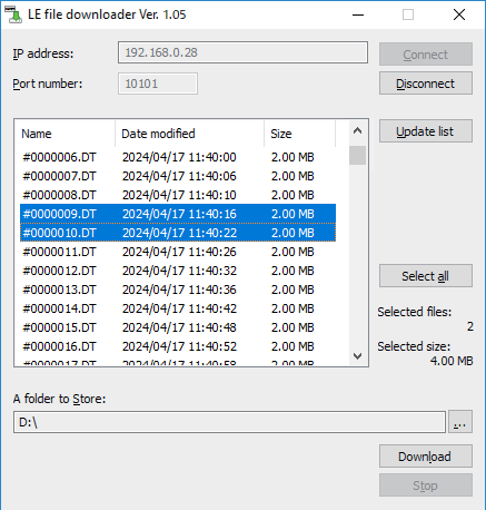
In addition to the conventional USB connection, it supports remote monitoring via Wi-Fi connection. You can use the AP mode in which the analyzer itself becomes a Wi-Fi access point and the STA mode in which the analyzer connects via a nearby access point. In addition, communication log files recorded on the SD card can be retrieved via Wi-Fi without stopping the measurement operation in logger mode. On your PC you can check the time stamp of the log file only when you need it and to check the communication record before and after the problem occurred without stopping the logging.
By connecting it to your PC by Wi-Fi, you can check the log files recorded on the SD card without stopping measurement in logger mode.
You can use the included utility software lefiledownload to list log files and download the specified file.
Supports RS-232C/RS-422/RS-485 (Standard Feature)
The device comes standard with RS-232C/RS-422/RS-485 interfaces, which are used widely in medical equipment and electronic products. RS-232C interface supports 11 lines including control lines and Sync transmission/reception clocks, and it is able to operate the control lines automatically at Simulation function. RS-422/485 interface is able to control the driver automatically at Simulation function.
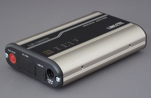
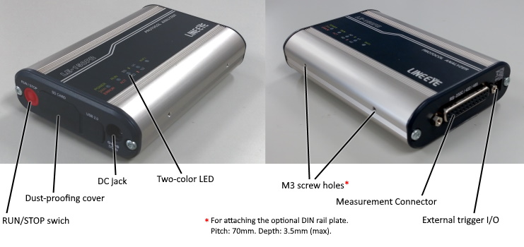
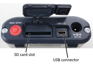
■ Explanation of each part
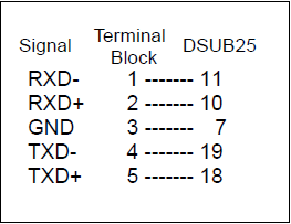
■ Pin Assignment of Connector (DSUB 25pin)
| Pin | Signal | Pin | Signal | |
|---|---|---|---|---|
| 1 | FG | 14 | - | |
| 2 | RS-232C SD | 15 | - | |
| 3 | RS-232C RD | 16 | - | |
| 4 | RS-232C RS | 17 | - | |
| 5 | RS-232C CS | 18 | RS-422/485 TXDB+/TR+*2 | |
| 6 | RS-232C DR | 19 | RS-422/485 TXDA-/TR-*2 | |
| 7 | GND*2 | 20 | RS-232C ER | |
| 8 | RS-232C CD | 21 | - | |
| 9 | +5VDC*1 | 22 | RS-232C CI | |
| 10 | RS-422 RXDB+*2 | 23 | - | |
| 11 | RS-422 RXDA-*2 | 24 | - | |
| 12 | - | 25 | (DC IN)*3 | |
| 13 | - |
Do not allocate power supply of more than 6V to its 9/10/11/15/13/18/19 pin on the Dsub 25pin connector. It may cause the product malfunction.
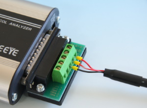
■ RS-485 Connection Image
Supprts TTL level communication with an option.
With an optional TTL probe pod (OP-5M), it can monitor TTL-level communication at 2.5V/ 3.3V/ 5V. It is useful such as when measuring TTL signals on an UART port of PCB and communication units.
About OP-5M
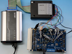
Measurement linked with an external device is available
You can use the external trigger input/output terminal to trigger by a change in an external signal or to transmit a specific communication status to an external measuring instrument as a trigger.
| Signal | Function |
|---|---|
| TRGIN | External trigger input |
| TRGOUT | External trigger output 1 |
| TRGOT2 | External trigger output 2 |
| GND | Signal ground |
Support Async PPP communication
Support Async and PPP communications. It is possible to select bit transmission order, polarity, and able to analyze efficiently.
< Monitoring Async >
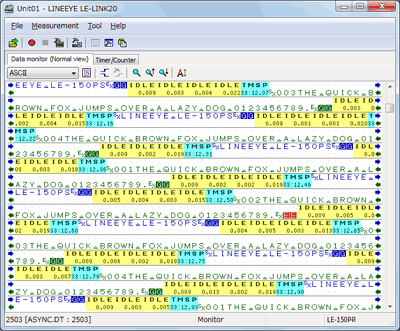
< Monitoring with Control Lines >
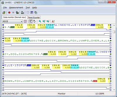
< ASYNC/SYNC Display in each frame >
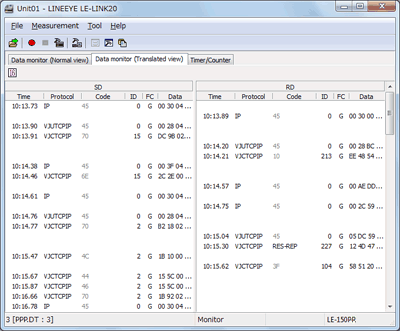
< Translation Display >
■ Communication Errors can be detected with High Reliability
It can judge parity error, framing error, and BCC error of various block check codes. It can find the communication sequence in the event of an error, by setting an application-level error notification character string to the character string agreement criteria of the triggering function. It can notify an error to external devices and alert a communication error in the logger mode (with a panel LED lighting), by specifying an external trigger signal output and user-defined LED lighting as a triggering action.
Trigger Configuration (Example 1)
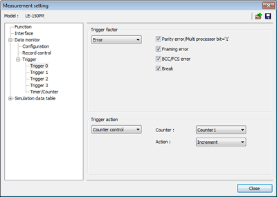
In this setting, if finding an error, "1" will be added in the "Conter1". Details of counters can be checked by selecting Timer/Counter window. And, the value of counter can be another trigger condition.
Trigger Configuration (Example 2)
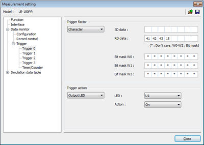
In this setting, if finding data of "41h, 42h, 43h, 15h", LED of U1 will be lighted. It is useful to check the flowing of specific data on the line without stopping the measurement.
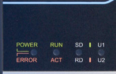
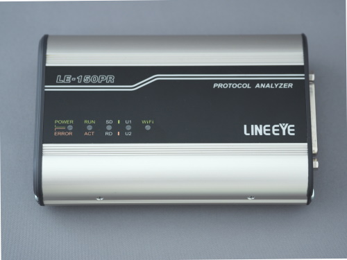
Lights of LED stands for:
| POWER/ERROR | Indicate the operating status of analyzer. |
|---|---|
| RUN/ACT | Indicate that analyzer is measuring or accessing to the SD card. |
| SD/RD | Indicate the status of SD line (green light) and RD line (red light). |
| U1/U2 | Able to light the U1 (green) /U2 (red) by trigger actions. |
■ Long Hour Recording
Measured data is saved as log files of the specified file size in the HDD of the PC (Remote mode) or in the SD card of the analyzer (Logger mode). It automatically records data until reaching the specified number of files, and then deletes the oldest file to record the new file. Also, it can stop measurement on reaching the specified number of files. It is useful for detecting any hindrance in the line.
| Baud Rate | Capacity: 2G byte (e.g. 2M byte×100 files) |
|---|---|
| 9600bps | Approx. 120 Hours |
| 230.4Kbps | Approx. 5 Hours |
< Record Control Setting in Remote mode >
< Record Control Setting in Logger Mode >
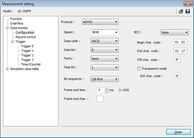
■ Measures at Arbitrary Speed
Monitor data at any speed by setting the baud rate of any four digits. The high-precision timer makes it possible to record idle time and time stamps along with data, and is not related to the performance of the PC.
< Configuration Setting >
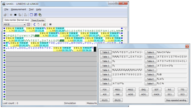
■Easy-to Operate Simulation Function
It incorporates an easy-to-use simulation function that makes it possible to transmit preset transmission data (16 types of data), or fixed data such as FOX messages, at the flip of a key while checking reception data.
< Example of Simulation >
■Schedule Measurement by Inner RTC
Real Time Clock (RTC) backed up by the battery of the analyzer makes it possible to specify the starting and ending times of the measurement. After the measurement, it turns off the power automatically and saves on power consumption.
< Auto RUN/STOP Setting >
Example of Use 1
< Configuration of Example2 >
Measure while the factory runs operation from 9:00 to 17:30.
| Saving Mode | Append |
|---|---|
| Max Files | 450 |
| File Size | 4M |
| Mode | Daily |
| Run Time | 9:00 |
| Stop Time | 17:30 |
| Power On Run | off |
LED of the analyzer will start blinking at 8:59 and be ready for measurement. It will start measuring at 9:00 and record data in the SD card for 450 files (4M each) as a ring buffer. It will stop measuring at 17:30 and turn off the power automatically to save on power consumption.
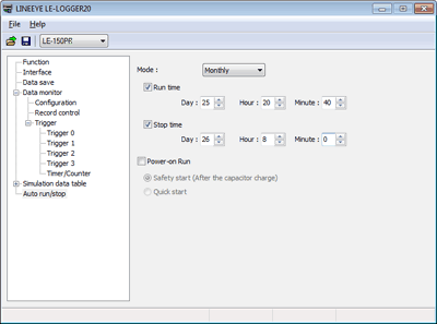
Example of Use 2
< Configuration of Example2 >
Equipment communicates with other equipment while it receives power from a power supply randomly.
| Saving Mode | Append |
|---|---|
| Max Files | 500 |
| File Size | 1M |
| Mode | Daily |
| Run Time | non |
| Stop Time | non |
| Power On Run | on (safety start) |
In this care, it is necessary to prove power to the analyzer from the same power supply for the equipment. Safety start will start measuring approximately 40 seconds (LED will be blinking) after powering on the analyzer for charging the capacitor for back-up data. Communication logs will be saved in the SD card for 500 files (1M each) endlessly. The analyzer will stop measuring when the power is not supplied for more than 1 second after saving data in the SD card.
■ Seamless Access to Communication Log Files
Communication log files can be viewed in detail on a PC. It offers seamless operation that handles a single measurement log file even when all files are read collectively. The measured data can be converted into text or CSV format to use in a word processor and/or spreadsheet software.
< Text Conversion Setting >
[ Example of Text Converted Data ]
*===============[2017-06-06 00:02:00]=*
* Model     : LE-150PR                *
* Version   : 1.00                    *
* Serial No.: ********                *
* Start time: 2017-06-06 00:00:00     *
* Stop time : 2017-06-06 00:01:00     *
*-------------------------------------*
* MONITOR DATA                        *
*  PROTOCOL: ASYNC                    *
*  S-SPEED : 9600    R-SPEED : 9600   *
*  CODE    : ASCII   CHAR BIT: 8      *
*  PARITY  : NONE    STOP BIT: 1      *
*  BCC     : NONE                     *
*                 PRINT CODE : ASCII  *
*=====================================*

SD:[ IDLE ][ TMSP ] - - - - - - - - - - - - - - - - - - - -
   [ 0384 ][060810]
RD:                3131323030303030323036303133303031303030
                    1 1 2 0 0 0 0 0 2 0 6 0 1 3 0 0 1 0 0 0

SD: - -[ IDLE ][ TMSP ]06[ IDLE ][ TMSP ] - - - - - - - - -
       [ 0015 ][060810]AK[ 0467 ][060811]
RD:0D0A                 -                313132303030303032
   CRLF                                   1 1 2 0 0 0 0 0 2

SD: - - - - - - - - - - - - -[ IDLE ][ TMSP ]06[ IDLE ][ TM
                             [ 0015 ][060811]AK[ 0411 ][060
RD:30373031333030313030300D0A                 -
    0 7 0 1 3 0 0 1 0 0 0CRLF

SD:SP ] - - - - - - - - - - - - - - - - - - - - - -[ TMSP ]
   812]                                            [060812]
RD:    31313230303030303230383031373730313030300D0A
        1 1 2 0 0 0 0 0 2 0 8 0 1 7 7 0 1 0 0 0CRLF

SD:15[ IDLE ][ TMSP ] - - - - - - - - - - - - - - - - - - -
   NK[ 4725 ][060820]
RD: -                31313230303030303230393031373530313030
                      1 1 2 0 0 0 0 0 2 0 9 0 1 7 5 0 1 0 0

SD: - - -[ IDLE ][ TMSP ]06[ IDLE ][ TMSP ] - - - - - - - -
         [ 0072 ][060820]AK[ 0651 ][060821]
RD:300D0A                 -                3131323030303030
    0CRLF                                   1 1 2 0 0 0 0 0
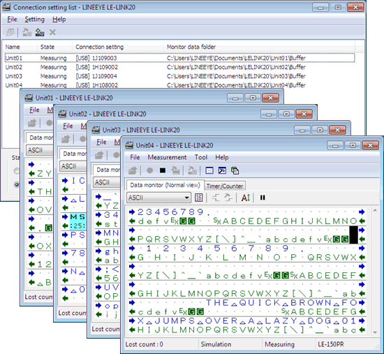
Control multiple analyzers by one PC software.
PC link software (LE-LINK20) included with the product controls multiple analyzers at the same time, and displays data in the separate measurement windows.
Can be used in Various Situation
■ Acquired Patent in Japan
A newly developed Instant Power Failure Prevention circuit with a Super Capacitor protects important communication log files stored in the SD cards. It protects data in case it occurs the power failure during recording to the SD card. Also, you can select the restart method of measurement from "Instant Start" or "After Charging Super Capacitor". Thus, continuous recording is possible while considering the status of data generation and power system.
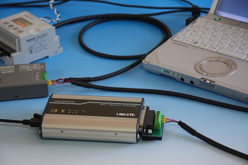
■ Small and Robust Housing Suitable for Severe Field Environments
The palm-sized robust unit can be used between -10 to +55°C. It operates not only on USB bus power, but also on external DC power of 7 to 34V. The consumption current is as low as 100mA at DC12V input. The SD card slot and the USB connector are equipped with a dust-proof cover that allows 2-way operation. It can be fixed easily to the equipment to be examined or built into an inspection line, since it is compatible with 35mm DIN rails.
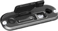
< Dust-proof covers >
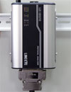
< DIN Rail Installation Example >
■ Automatically Switches between Japanese and English
The system language alternates automatically between English and Japanese according to that of OS. This facilitates introduction of the software to development bases outside Japan.