LE-8500X-RT
LE-8500XR-RT
●Supports RS-232C, RS-530, RS-422 / RS-485, and TTL just by one unit.
●Supports legacy interfaces such as V.35, X.20 / 21, RS-449.
●Program simulation function that enables flexible communication tests
●Bit error rate test function for transmission quality analysis
●Reproduces and outputs a timing waveform data acquired by the logic analyzer function
●Time stamp that allows time synchronization by GNSS (PPS) signal
●Automatically records communication logs to large-capacity external storage via USB3.0
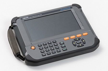
●1kg, handheld design. Measurement can be performed by itself without a PC
●Saves measurement reports in snapshot or text format
●PC link by LAN, USB, or Wi-Fi (XR only) connection
LE-8500X-RT No Wi-Fi connection
LE-8500XR-RT With Wi-Fi connection
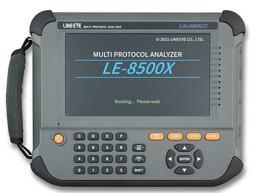
The LE-8500X-RT/LE-8500XR-RT is a multi-protocol analyzer that can measure and test RS-232C, RS-530, RS-422/RS-485 and TTL level serial communication as a single unit.
It can be widely used for the development and maintenance of serial interfaces of PC peripherals and FA devices, UART, SPI, I2C, etc. of embedded boards by using the monitor function, communication simulation function, bit error rate function, etc. according to the test situation.
The model is equipped with a 7-inch wide-color LCD with a touch panel, thus you can check the measurement data immediately on-site without using a personal computer. You can log the data to a USB flash memory etc. via USB 3.0, thus you can analyze the data in detail after the measurement.
In addition, as the time stamps that are time-corrected with high accuracy by GNSS signals can be added to the monitor data by using an optional GPS antenna, by checking the time stamps you can compare and analyze the data measured simultaneously at two points for a long period of time to investigate a communication failure.
Furthermore, by replacing the standard measurement board with a LAN measurement board (sold separately), it can also be used for Ethernet networks. With just one unit, it can be used for many years from PC peripherals and embedded devices to communication fields where reliability is important, such as railways, aviation, and various production lines.


| Interface | RS-232C,RS-530,RS-422/RS-485,TTL(1.8V/2.5V/3.3V/5V level) |
|---|---|
| Interface Expansion | Measurement board can be replaced with optional measurement board |
| When using optional SB-FE2 | 100BASE-TX/10BASE-T (zero delay, EtherCAT supported) |
| When using optional SB-GE2 | 1000BASE-T, 100BASE-TX, 10BASE-T, PoE |
| When using optional SB-T1E | 100BASE-T1, 10BASE-T1L, 10BASE-T1S, PoDL / SPoE |
| When using the optional SB-C2AN | CAN / CAN FD, analog measurement |
| Standard protocol | ASYNC (Asynchronous), ASYNC-PPP Character synchronous SYNC/BSC Bit synchronous HDLC/SDLC/X. 25 CC-LINK ,Modbus ,PROFIBUS I2C, I3C*2, SPI, BURST*3 |
| Synchronous clock | TXC1 (DTE transmission clock), TXC2 (DCE transmission clock), RXC (DCE reception clock), AR (The synchronous clock extracted from the edge of the transmission and reception data) |
| Capture memory | 1Gbyte*4 2-split use, accidental erasure prevention protection, and selection of ring buffer or fixed size buffer are available. |
| Backup memory | Measurement conditions and part of the latest data (about 16M bytes) can be automatically saved*5 |
| RTC back-up | Keeps the date and time of the real-time clock IC for about 5 years by the built-in lithium battery. |
| Max. speed*6 | Full duplex: 10Mbps / Half duplex: 20Mbps / SPI: 30Mbps (Up to 15Mbps for the slave mode simulation) |
| Speed setting range | Normal mode: 50bps to 12Mbps High-speed mode*6: 50bps to 20Mbps. (Up to 30Mbps for only SPI.) |
| Speed setting step and accuracy | Can freely set four effective digits, separately for transmission and reception.(Margin of error: ±0.01% or less) |
| Data format | NRZ, NRZI, FM0, FM1,Manchester0,Manchester1 |
| Data code | ASCII, EBCDIC, JIS, Baudot, Transcode, IPARS, EBCD, EBCDIK, HEX*7 |
| Character framing | ASYNC : Data bit (5,6,7,8) + parity bit (0,1) + stop bit (1,2) Character synchronous : Data bit + parity bit (6 or 8 bits in total) Bit synchronous : Data bit (8 bits) |
| Parity bit | NONE, ODD, EVEN, MARK, SPACE |
| Multi-processor bit | MP (multiprocessor) bit is shown with a special mark. |
| Bit transmission order | LSB first or MSB first (switchable) |
| Polarity inversion | Normal or Inverted (switchable) |
| Error check | Parity (ODD, EVEN, MARK, SPACE), Framing, Break, Abort, Short frame, BCC (LRC, CRC-6, CRC-12, CRC-16, CRC-ITU-T, FCS-16, FCS-32), and BCC transparent mode can be selected. |
| Online monitor function | Communication log is recorded continuously and displayed in the LCD without affecting the communication lines. |
| Idle time display | OFF (no record); Resolusion: 100ms, 10ms, 1ms, or OFF can be selected.; Max 999. 9 sec |
| Time stamp display | The reception time is added as timestamp data for each received frame. Resolution: Year Month Date Minute / Month Date Minute Second / Date Minute Second 10msec or elapsed time 100µsec/10µsec/1µsec (max.134217727) Time adjustment by GNSS PPS signal or external PPS signal is available*8 |
| Line status display | Records and displays the wave form of 7 signals, RTS, CTS, DTR, DSR, DCD, RI, TRG (external trigger input) along with the transmission / reception data. |
| Address filter | Records only frames of the specified address. (only when HDLC / SDLC / X.25) Normal mode: 1byte High-speed mode: 2byte can be specified |
| Data display and operations | Pause in capture, scroll, paging, jump to the specified screen. |
| Bit shift display | Entire frame can be shifted to the right or left in 1 bit increments. |
| Protocol translation display | SDLC (modulo 8/128), ITU-T X.25 (modulo 8/128), LAPD, PPP, BSC, I2C, Modbus, User Defined Translation |
| Line status LED | Status LEDs for TXD,RXD, RTS, CTS, DTR, DSR, DCD, RI, TXC1,TXC2,and RXC |
| Interval timer | 4kinds; Max. count: 999999 (Resolution: 1ms ,10ms ,100ms) |
| General-purpose counter | 4kinds; Max. count: 999999 |
| Data counter | For TXD and RXD (1 each): Max. count: 4294967295 |
| Trigger function | Up to 8 pairs of trigger conditions and actions can be specified. Sequential actions, which validate another condition after one condition is satisfied, are possible. |
| condition | Communication error (Parity, MP, framing, BCC, break, abort, short frame can be specified individually.), communication data string up to 8 characters (don't care and bit mask available), idle time more than the specified duration, match time/counter value, logic status of interface signal line and extarnal trigger input |
| action | Stops measurement/test (number of offsets until a stop can be set), validates trigger conditions, controls timer (start/stop/restart), controls counter (count/clear), activates buzzer, saves monitor data on a external storage device (SD card/USB memory), sends the specified character string (during manual simulation), and sends pulse output to external trigger terminal OT2. |
| External trigger output | Sends pulse output to external trigger terminal OT1 when all conditions are satisfied. Sends pulse output to external trigger terminal OT2 when the trigger action is set so. |
| Data search function | Retrieves the data with specific condition from capture memory. |
| condition | Communication error (parity, MP, framing, BCC, break, abort, short frame can be specified individually), communication data string up to 8 characters (don't care and bit mask available), idle time more than the specified duration, specified time stamp, time stamp of the specified time (the time range can be specified), and trigger matching data |
| action | Shows the match data at the top or enumeration display (selectable) |
| Mark jump | You can add marks (up to 9 points) to the data in the capture memory and jump to the marked position. |
| Monitor conditions auto setting | Measurement conditions such as protocol, transmission speed, (max. 1.544Mbps), framing, data code, synchronous character and BCC check can be automarically set.*9 |
| Auto run/stop function | It can automatically start and finish measurement at the specified time at the selected repeating cycle (monthly, daily, hourly). |
| Power ON auto run function | It can automatically start measurement when the external power is turned ON. |
| Auto Backup function | You can select whether or not to automatically save the measured data at the end of the measurement. Save destination: Built-in eMMC (approximately 16M bytes of latest measurement data) or an external storage device (all measurement data) can be selected. |
| Auto save function | Automatically saves the monitored data in the capture memory and saves as communications log file into an external storage device (SD card/USB memory). Restart mode and Append mode (which are ring save operation) and Max mode (in which the measurement stops at the specified capacity.) can be selected. |
| File size | BUF (capture memory size) , 1MB , 2MB , 4MB , 8MB , 16MB, 32MB, 64MB, 256MB |
| MAX. files | 2048 (max. 2Tbyte) |
| Delay time function | Measures and displays the interval of change in the interface signal line. (current/min/max/average, resolution: 0. 1ms) |
| Signal voltage measurement function | Measures and displays the value of voltage amplitude: |
| Statistical analysis function | Takes statistics of each specified time (1 second to 240 minutes) and displays graphs of transmission/reception data, number of frames, and satisfied trigger condition count. |
| Logic analyzer function | Measures the logical change of the interface signal in the sampling clock period, and displays its wave. |
| Sampling clock | 1KHz to 200MHz (17 steps) (200MHz is supported by firmware version 1.08 or later.) |
| Sampling memory | Max 4096 |
| Trigger condition | Logical status match between interface signal line and external signal. Match of the specified trigger conditions of ONLINE monitor functions |
| Trigger position | Before, center, after |
| Trigger pass count | You can specify the number of times (0 to 9999) to pass (ignore) the trigger condition match |
| Zoom in/out | ×10, ×5, ×2, ×1, ×1/2, ×1/4, ×1/8, ×1/16, ×1/32, ×1/64 |
| Other functions | Time measurement between the cursors, signal line exchange, signal status search |
| Bit error rate test | Conforming to ITU-T G.821 it measures line quality such as bit error rate and block error rate*11. |
| Communication mode | Synchronous (SYNC) or Asynchronous (ASYNC) can be selected. RTS/CTS flow control is available. |
| Measurement speed | 50bps to 4.3Mbps*12, freely set by four effective digits |
| Measurement mode | Continuous measurememt, specifies the number of receiving bit, specifies the time to measure, repeatedly measurement at the unit of 1 - 1440 min |
| Test pattern | 26-1, 29-1, 211-1, PN15, PN20, PN23, MARK, SPACE, ALT, DBL-ALT, 3in24, 1in16, 1in8, 1in4 |
| Flow control | Flow control for RTS and CTS is available. |
| Error bit insertion | Inserts 1-bit or 5-bit error in test pattern by key operation. |
| Measurement range | It is able to measure the parameter of the ITU-T advice G.821. Effective received bit (0 to 9999999sec), bit errors (0 to 9999999 to 9.99E9), bit error rate(0 to 9. 99E-9 to 1), block errors (0 to 9999999 to 9.99E9), block error rate (0 to 9.99E-9 to 1), Savail(available measurement time: 0 to 9999999sec), loss count (synch loss: 0 to 9999), error duration (0 to 9999999sec), %EFS (normal operation rate: 0. 000 to 100. 000%) |
| Simulation function | Transmission/reception test of arbitrary data in DTE or DCE mode (pin assingnment can be switched) is avaialble. |
| Transmit data entry | Transmit data entry: Register 160 kinds of transmission data tables (10 Groups x 16, total 16K data) |
| Error data entry | A part of transmission data can be registerd as error data such as parity error. |
| Line auto control | Auto (Controls transmission timing with RTS, CTS, DTR, DCD signal lines automatically in 1 ms resolution) or manual control (key operation) can be selected. |
| Transmit driver control | When simulating RS-485, the automatic control that automatically activates the driver only before and after data transmission and the manual control that interlocks with [SHIFT] + [F] operation of DTR or DCD signal are available. |
| Half duplex mode | Normal mode: When using for RS-485, the analyzer's transmission data and the reception data of the other device are displayed on the TXD side/RXD side. High-speed mode: When using for HDLC of RS-485, match/mismatch frame of address filter is displayed on TXD side/RXD side. |
| MANUAL mode | Sends the data assigned to operation keys each time a key is pressed, while checking communications status on the display. Can be used together with the trigger function |
| FLOW mode | Simulates the X-on /X-off control data and flow control procedures of RTS/CTS control line. (To be sender or receiver is selectable).*13 |
| ECHO mode | Returns reception data in frames (buffer echo), in bytes (character echo), or by looping back (loopback echo). |
| POLLING mode | Simulates polling communications procedures. (To be slave or master is selectable.) |
| BUFFER mode | Reproduces transmission of selected data (SD or RD) captured in memory by monitor function. |
| PROGRAM mode | Creates a simulation program (Max. type: 4, Max steps: 512) using the dedicated commands (47 types) to test the communication procedure. |
| PULSGEN mode | Outputs a timing waveform data communication line measured by the logic analyzer function or edited waveform data. |
| File management function | Measurement data and condition can be saved in a SD card or USB flash. And the format of the data/condition can be used in a PC. |
| File types | Measurement data (.DT), all measurement conditions (.SU), trigger save data (TGSAVEnn.DT), auto save data (#nnnnnnn.DT), and screenshot (date_time.PNG), text conversion (.txt, .csv) |
| File controls | Normal file display, file display by specified type/created date basis, save, load, delete, delete all. |
| Storage device | 2G to 32G byte SD/SDHC card (only the optional SD card sold by LINEEYE are supported.), a USB flash memory, or a SSD of USB3.0 interface*14 |
| Remote Control | Key emulation software "LE-PCKEYEMU" is attached. PC link software "LE-PC800X" is available*14 The Library to control the analyzer is available. |
| Print out*15 | Measurement data can be printed continuously in various formats, and display images can be printed as hard copies. |
| LCD | 7 inch TFT color display with capacitive touch panel |
| LAN port | RJ45 connector, 1000BASE-T Ethernet: IEEE 802.3, for PC connection |
| USB device port | Type C connector, supports SuperSpeed transfer.For PC connection |
| USB host port | Standard A-connector, supports SuperSpeed transfer. For an external storage (USB memory/SSD). |
| SD card slot | Standard size for SD/SDHC memory card. Compatible with the standard of SD association. |
| External I/O terminal | 5-pin in the bottom row of 2-row pin header connector, for trigger I/O of TTL level |
| GPS antenna connector | SMA (female) connector |
| Wi-Fi Connection*16 | IEEE 802.11 b/g/n for PC connection Frequency range: 2412MHz to 2484MHz Transmission power: +18.5dBm(802.11b), +18.0dBm(802.11g), +17.0dBm(802.11n) |
| Power supply | Attached AC adapter |
| Built-in battery | Lithium-ion secondary battery (Model: P-26LW2) |
| Battery operating time | About 4 hours*17. Can be further extended by using power saving functions (auto brightness dimming, auto power off) |
| Battery charging time | By the AC adapter with the unit is turned off: About 3.5 hours By a USV charger with the unit is turned off: About 4.5 hours |
| Temperature range | In operation : 0 to 40 degree Celsius, In storage : -20 to 50 degree Celsius |
| Humidity range | 20 to 85%RH (no condensation) |
| Standard | CE(Class A),EMC( EN61326-1:2013 ) |
| Dimension, mass | 234 ( W ) x 186 ( D ) x 44 ( H ) mm, About 990g |
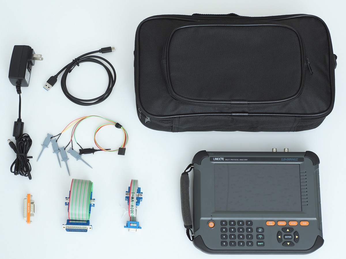
| Accessories | Monitor cable for DSUB 25-pin (LE-25M1), Monitor cable for DSUB 9-pin (LE-009M2), DSUB25pin-9pin conversion adapter, 5 wires TTL prove cable (LE-5LS), USB cable (Standard A - Type C), AC adapter (6A-181WP09), carrying bag (LEB-01), Utility CD, quick start guide, and warranty |
In high-speed mode, all capture processing of communication data is performed by hardware, so data can be reliably recorded without capture loss even in high-speed communication with a high transfer rate. However, the high-speed mode is only compatible with the monitor function, MANUAL simulation function, logic analyzer function, and PULSGEN waveform editing output function, and cannot be used with the asynchronous PPP, character synchronous SYNC/BSC, Modbus, I2C, and BURST protocols. In addition, there is no monitor condition automatic setting, idle time, control line recording, timer/counter display, and available trigger conditions are only send/receive data match trigger, error trigger, and external signal trigger, and available trigger operation is measurement stop or external signal output.
<Standard Accessories>